VMWare
Syntax for Files
http://sanbarrow.com/vmx.html (all minor details are available on this website)VMWare Tools Patch for any OS
http://www.astroarch.com/virtual/patches.htmlOpen Source Firewall solution
http://www.smoothwall.org/VMware Backup solution:
http://www.phdvirtual.com/How to Install VMware ESX 4.0 on Workstation 6.5.2 as a VM
http://xtravirt.com/xd10089VMware ESX Server Updated Samba RPMs
http://www.astroarch.com/virtual/samba.htmlScanner:
http://nessus.org/Latest upto date info @
http://www.getyournerdon.com/chris/default.aspx
Most of the Documents can be found here -
http://www.vmware.com/support/pubs/
Ten steps to a Windows Server 2003 virtual cluster configuration
This tutorial demonstrates 10 easy steps to configuring and simulating a Windows Server 2003 cluster on your desktop using VMware Workstation.
You will need a trial or licensed version of VMware Workstation. Download a trial copy of VMware Workstation, follow the wizard, install VMware Workstation and reboot. After completing the following steps, you will have successfully configured a virtual cluster.
Step 1: Create a virtual environment
Step 2: Add network cards to the cluster nodes
Step 3: Create a private network configuration
Step 4: Configure a public network connection
Step 5: Configure shared disks in VMware Workstation
Step 6: Edit the VMX file for each cluster node
Step 7: Boot into the BIOS
Step 8: Configure the drives on the virtual machine
Step 9: Configure the cluster service on a Windows 2003 Server
Step 10: Test the Windows 2003 cluster
Create a virtual environment
The first step is to prepare the virtual environment to work with clustering. to create a clustering solution, you will need to do the following:
- Create, install and configure a virtual Windows 2000 or Windows 2003 domain controller with domain name server (DNS) installed and configured. When creating Windows 2003 virtual machines, accept the default of LSI Logic Adapter in the New Virtual Machine wizard.
- Create, install and configure two VMs with Windows 2000 Advanced Server or Windows 2003 Server Enterprise Edition.
- Ensure that any VM participating in the cluster has a public and private network configuration. Each node will need two network cards -- each with a public IP address and a private IP address.
- Ensure that all of these virtual servers have static IP addresses.
- Ensure that VMs that are going to represent the nodes of the cluster are joined to the domain.
- Have access to the Windows 2000 Advanced Server CD-ROM or copy the I386 directory to the VM.
- Have access to the Windows 2003 Enterprise Edition CD-ROM or copy the I386 directory to the VM.
- Create a domain user account on the domain controller, such as Cluster_Service. This account will be used to run the cluster service.
Once you have the environment configured, the next step is to add additional network cards to the nodes that will participate in the cluster.
Add network cards to the cluster nodes
Once you have created the disks, you also need to run the hardware wizard and add a second Ethernet adapter to each virtual machine that will be participating in the cluster.
- Highlight the applicable virtual machine and edit the virtual machine settings.
- Click Add on the hardware tab.
- Select Ethernet Adapter.
- Click Finish to add the adapter.
The VMware Control Center will display the additional network card as shown in Figure 1.
Figure 1 VMware Control Center displaying the additional network card. (Click on image for enlarged view.)
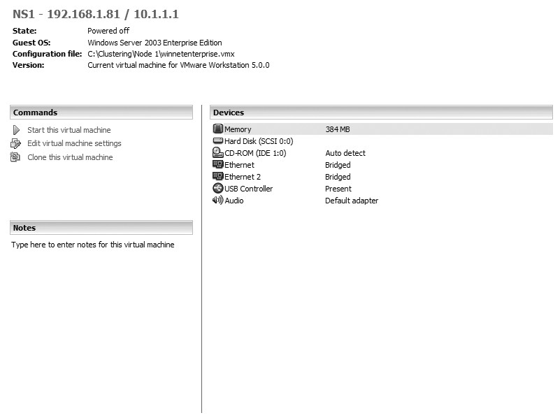
| Note: For the purpose of this example, we are using a bridged network connection for all Ethernet Adapters. |
For clustering to work properly, you must configure two network cards on each VMware Workstation virtual server. The private network allows for communication between each of the nodes, commonly known as the heartbeat. Follow these instructions to add a network card:
- Open VMware Workstation from the start menu.
- Select Settings from the VM menu.
- Choose Add and select Network Adapter.
- Click Next and select Bridged Connection.
- Click Finish.
The next time you power on the virtual server, it will have an additional network card. Repeat these steps on each VM that will be part of the cluster.
(For example, assume that you have two VMs [swcluster1 and swcluster2]. Once additional network cards have been added, you will have to configure them for the heartbeat connection. You might configure your heartbeat on node 1 [swcluster1] with the IP address 10.1.1.2, and on node 2 [swcluster2] with the IP address 10.1.1.3. )
When you set up the static IP address, it is important that you select the Advanced tab in the TCP/IP properties dialog box and choose Disable NetBIOS over TCP/IP, as shown in Figure 2. All cluster nodes communicate via TCP/IP only. If you do not choose this option, problems may occur with node-to-node communication.
Figure 2 Choose Disable NetBIOS over TCP/IP in the Advanced tab. (Click on image for enlarged view.)

Configure a public network connection
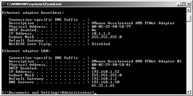
To configure your public network connection, right-click on your second network card and assign the appropriate IP address, DNS and WINS settings. To verify connectivity, open a command prompt and type <>ipconfig /all (as shown in Figure 3) on each node in the cluster to verify the configurations. When each node is properly configured with a private and a public network address and connectivity has been tested, the next step is to make sure that each node is connected to the domain.
- Right-click on My Computer.
- Click on the Network Identification tab (on both clustered machines).
- Verify that you are connected to the desired Active Directory domain.
- Power down both nodes, leaving the domain controller running.
Before you begin to install clustering, you must know your virtual server's name and the IP address you are assigning to the cluster.
Figure 3 Verifying connectivity. (Click on image for enlarged view.)
Configure shared disks in VMware Workstation
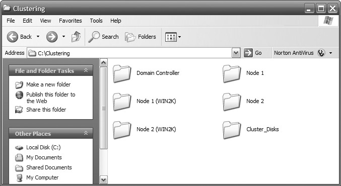
To configure your shared disks, create a folder on your hard drive and label it accordingly. For this example, we will call the folder Cluster_Disks, as shown in Figure 4.
Figure 4 Create a folder on your hard drive and label accordingly. (Click on image for enlarged view.)
Next, highlight any one of the three VMs you created in the favorites window and edit virtual machine settings. In the Virtual Machine Settings window, click Add to start the Add Hardware Wizard and do the following:
- Choose Hard Disk on the Hardware Type window.
- Click Next.
- On the Select a Disk window, choose Create a new virtual disk.
- Click Next.
- On the Select a Disk Type window, accept the default of SCSI (recommended).
- Click Next.
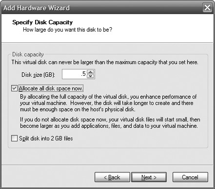
The Specify Disk Capacity screen is where you will size the virtual disk. Make sure to size this according to your needs. When you have finished sizing the disk accordingly, select the Allocate all disk space now checkbox as shown in Figure 5.
Figure 5 Select "Allocate all disk space now". (Click on image for enlarged view.)
Click Next and view the folder where your shared disks will be stored (Figure 6). Click Finish to create the shared disk. Depending on the size of the disk, this can take a while to create (Figure 7).
Figure 6 Browse to the folder where your shared disks are stored. (Click on image for enlarged view.)
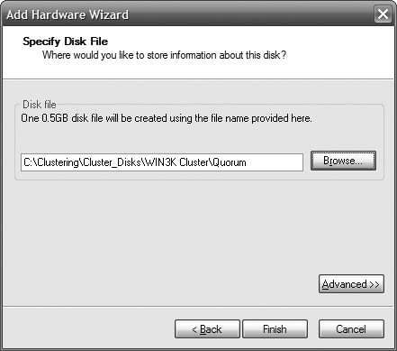
Figure 7 Shared disc creation may take some time. (Click on image for enlarged view.)

After the disk has been created, highlight the disk on the Hardware tab and click Remove, as shown in Figure 8. The first disk we created was the quorum disk. Next, we will create two more shared disks. This will allow for a configuration of an active/passive cluster or an active/active cluster. Repeat the process to create two additional shared disks.
Figure 8 Highlight the disc on the hardware tab. (Click on image for enlarged view.)
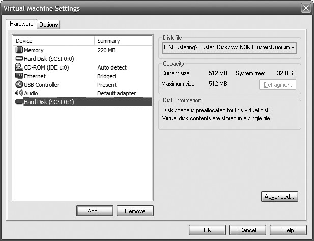
| Note: It is very important to remove the disk from the Hardware tab after it is configured. Do not forget to do this. Highlight each disk you created and click the Remove button. |
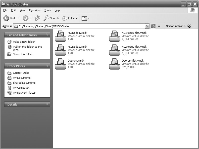
Figure 9 Disk configuration. (Click on image for enlarged view.)
Edit the VMX file for each cluster node
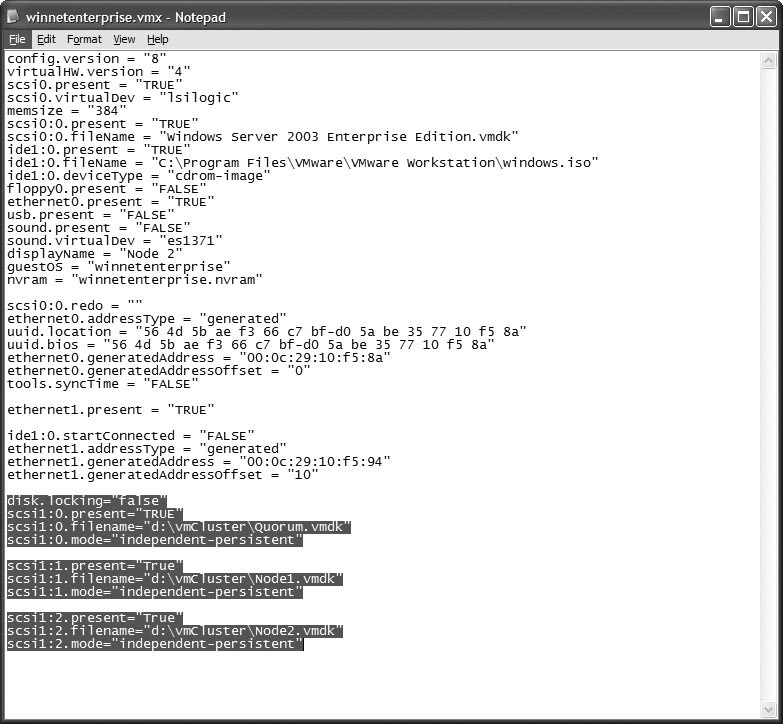
Now that the shared disks have been created, the VMX or VMware Configuration file must be modified for each node that will participate in the cluster. To edit the *.vmx file, browse to the location of your VMs and open the file (.vmx) in Notepad. Figure 10 illustrates how to open a *.vmx file in Notepad.
Figure 10 How to open a *.vmx file in Notepad. (Click on image for enlarged view.)

| Note: Do not attempt this step if your VMs are running. Make sure they are powered off and that you have EXITED from the VMware Workstation program. Once you have exited the program, follow these steps. If you do not exit VMware Workstation, the shared disks will not boot properly and you will have to boot into the BIOS to correct the problem. |
disk.locking="false"scsi1:0.present="TRUE"scsi1:0.filename="path to vmdk file"scsi1:0.mode="independent-persistent"scsi1:1.present="TRUE"scsi1:1.filename="path to vmdk file"scsi1:1.mode="independent-persistent"
By adding the disk.locking="false", you allow the disk to be shared. Scsi1:0.filename is the location of your shared disk. Setting the disk to independent persistent safeguards the shared disk, as information is permanently written to the disk and is not affected by snapshots. For every disk you use, you must increase the number. Refer to this example:
SCSI1:0 will be the Quorum drive, SCSI1:1 will be another disk and SCSI1:2 will be the second disk. Therefore, you would add the following code to your configuration:
disk.locking="false"scsi1:0.fileName = "C:ClusteringCluster_DisksWIN3KClusterQuorum.vmdk"scsi1:0.mode = "independent-persistent"
scsi1:1.present = "TRUE"scsi1:1.fileName = "C:ClusteringCluster_DisksWIN3KClusterNS1Node1.vmdk"scsi1:1.mode = "independent-persistent"
scsi1:2.present = "TRUE"scsi1:2.fileName = "C:ClusteringCluster_DisksWIN3KClusterNS2Node2.vmdk"scsi1:2.mode = "independent-persistent"
Make sure that both VMs have *.vmx files updated with the appropriate syntax. Refer to figure 11 and figure 12, illustrate the *.vmx file on both VMs.
Figure 11 Illustrates the *.vmx file on one of the virtual machines. (Click on image for enlarged view.)
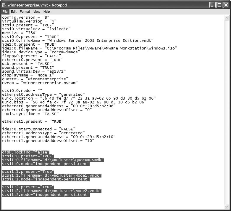
Figure 12 Illustrates the *.vmx file on one of the virtual machines. (Click on image for enlarged view.)
After the information is added to the virtual machine configuration files, the VMware Control Center will show you the new disk configuration and the disks will appear in the lower right-hand corner. Figure 13 and figure 14 illustrate the disk configuration and the virtual disks in action, respectively.
Figure 13 Illustrates the disk configuration. (Click on image for enlarged view.)

Figure 14 The virtual discs in action. (Click on image for enlarged view.)

Now you're ready to power on the first VM in the cluster. Don't activate both VMs at the same time. Power on the first one, configure the disks and install the cluster service before turning on the second VM.
Boot into the BIOS
If you power on your virtual machine for the first time and it tries to boot from a shared disk, you must turn each node to the basic input/output system (BIOS) to make sure the disks will load in the appropriate order. Power on the first computer and follow these steps:
- Choose F2 to enter the BIOS.
- Use the arrow keys to move to the boot menu.
- On the boot menu, move the arrows until the focus is on the hard drive.
- Hit Enter and make sure Disk (0:0) is at the beginning of the boot order.
When you configure a cluster, the boot disk goes last, so if you do not perform these steps you won't be able to boot your OS after adding the shared disks. Once you have Disk (0:0) at the beginning of the boot order, save your changes and repeat the process on the second node.
Configure the drives on the virtual machine
Once you've successfully added the shared disks, you can power up the first VM. To configure your drives, follow these steps:
- Right-click on My Computer.
- Select Manage. (This can also be accessed through Administrative Tools.)
- Under Storage, select Disk Management to open the Computer Management Console.
- When you go into Disk Management for the first time, you will be prompted to write the disk signature and upgrade the disk to a dynamic disk.
- Choose Yes to write the disk signature; choose No when asked if you'd like to upgrade the disk to a dynamic disk.
| Note: If you accidentally upgrade the disks to dynamic disks, don't worry -- you can simply right-click on the Disk box and choose Revert to Basic. |
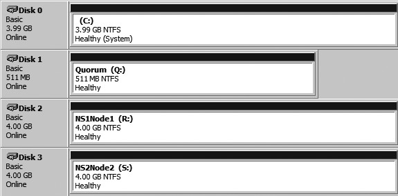
- Disk 1 will be the Quorum drive.
- Disk 2 will be the first instance data and log drive.
- Disk 3 will be the second instance data and log drive.
Figure 16 shows this disk configuration when it is complete.
| Note: We could have added two more drives as well to separate SQL Server's data and log drives. |
Figure 15 Can you see the unformatted shared disks via Disk Management? (Click on image for enlarged view.)
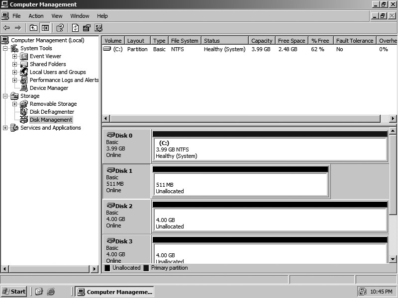
Figure 16 The completed disc configuration. (Click on image for enlarged view.)
Configure the cluster service on a Windows Server 2003
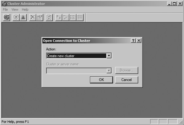
We are finally at the testing phase; this is the easy part. Start by clicking Start → All Programs → Administrative Tools → Cluster Administrator. The Cluster Administrator window will appear with an Open Connection to Cluster dialog box. Click the drop down menu and choose Create new cluster, as shown in Figure 17.
Figure 17 What you will see in the Cluster Administrator window. (Click on image for enlarged view.)
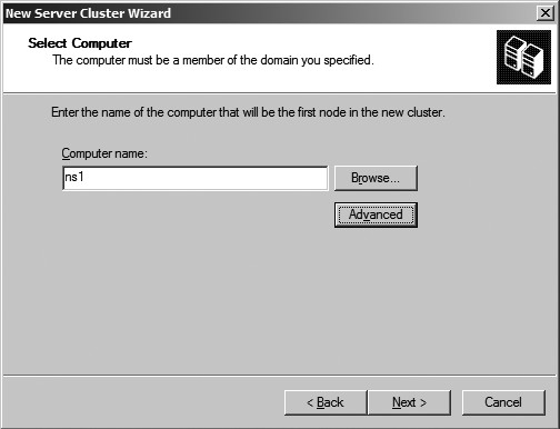
In the New Server Cluster Wizard, choose a valid cluster name and click Next to continue, as shown in Figure 18. After a valid cluster name has been entered, the computer name of the node participating in the cluster is populated (Figure 19).
Figure 18 New Server Cluster Wizard. (Click on image for enlarged view.)
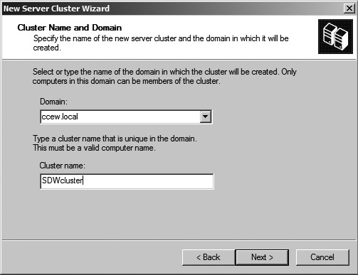
Figure 19 The computer name of the node participating in the cluster is populated. (Click on image for enlarged view.)
When the Analyzing Configuration window is open (Figure 20), the wizard does the following:
- Checks for existing cluster
- Establishes node connection(s)
- Checks node feasibility
- Finds common resources on nodes
- Checks cluster feasibility
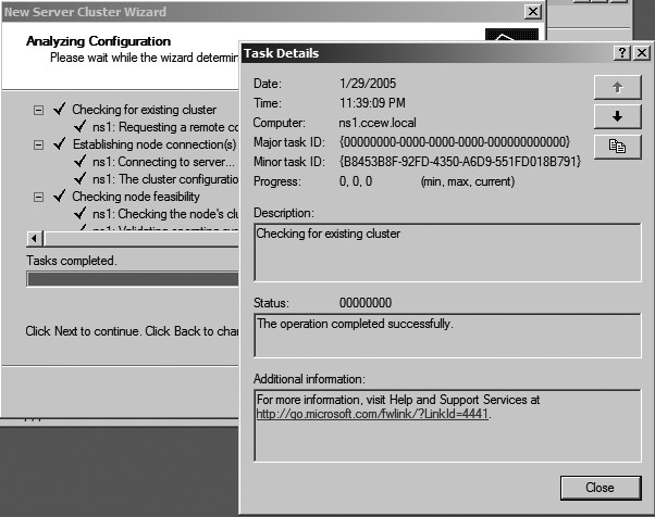
You can expand the "+" signs to make sure everything looks acceptable in your cluster, as shown in Figure 21. Additionally, you can view the log and details by selecting the appropriate button. If your cluster has problems, fix them as defined in the configuration and reanalyze.
Figure 20 The Analyzing Configuration window. (Click on image for enlarged view.)
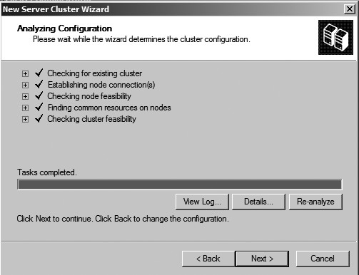
Figure 21 Expand the + signs to make sure everything in your cluster looks good. (Click on image for enlarged view.)
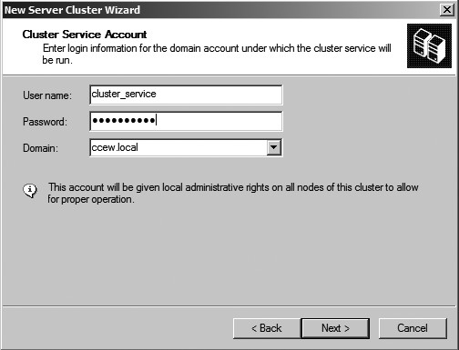
In the IP address window, enter the cluster IP address as shown in Figure 22. This will be the IP address to manage the cluster. While in the Cluster Service Account window, enter a valid domain user account that the cluster service will use (Figure 23). This account will be added to the local administrator group on all nodes of the cluster.
Figure 22 Input the cluster IP address. (Click on image for enlarged view.)
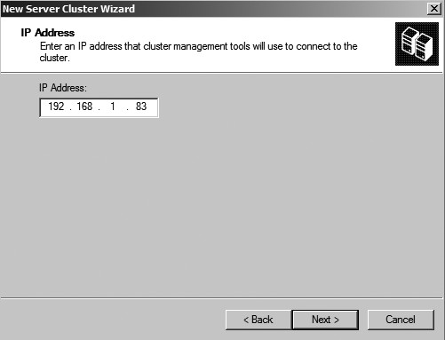
Figure 23 The Cluster Service Account window. (Click on image for enlarged view.)
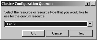
The Proposed Cluster Configuration window (Figure 24) allows you to review your configuration and make changes if necessary. Click on the Quorum button to make sure the right disks have been assigned (Figure 25) to the quorum. Click Next to create the cluster configuration.
Figure 24 The Proposed Cluster Configuration window. (Click on image for enlarged view.)
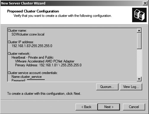
Figure 25 Click on the Quorum button to make sure the right disk have been assigned to the quorum. (Click on image for enlarged view.)
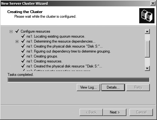
Once the cluster configuration process is complete, you can review the details by expanding the "+" signs. Figure 26 illustrates a completed cluster configuration. Click Next and Finish and you have successfully configured your first virtual node with a Windows 2003 cluster. The next step is to power on the second node.
Figure 26 Completed cluster configuration. (Click on image for enlarged view.)
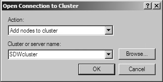
Click Start → All Programs → Administrative Tools → Cluster Administrator and the Cluster Administrator window will appear with an Open Connection to Cluster dialog box. Click the drop down menu and choose Add nodes to cluster and the cluster name, as shown in Figure 27. Click OK and the Welcome to the Add Nodes Wizard appears.
Figure 27 The Open Connection to Cluster window. (Click on image for enlarged view.)
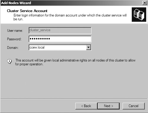
The computer name automatically populates the Computer Name text box in the Select Computer window. Click Add to add the computer to the list, as shown in Figure 28. The configuration is analyzed and, if there are no problems, you can continue to enter the Cluster Service Account window in the wizard, as shown in Figure 29.
Figure 28 Select computers window. (Click on image for enlarged view.)

Figure 29 The Cluster Service Account window. (Click on image for enlarged view.)
You will now be asked to review the configuration. Click Next and the node will be added to the cluster. Finally, click Finish. A virtual Windows 2003 cluster has now been successfully created.
Test the Windows 2003 Cluster
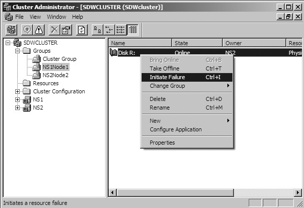
To test the failover process, right click on any group and choose Move group (Figure 30). If everything is configured properly, the group will move from its current node to the available node. Another test would be to move all of the groups to a particular node and then power off the VM that is currently active. You can actually see the failover occur. This would simulate a total shutdown or failure of a node. To simulate a failover:
- Expand the Groups folder.
- Highlight a group in the details pane.
- Right-click on the disk.
- Choose Initiate Failure (Figure 31).
You will see some minor activity and then the status will return to normal. This happens because the cluster will try to correct itself three times before failing over. You must initiate a failure four times in a row to have the disk move nodes.
Figure 30 Test the failover process by right-clicking on any group. (Click on image for enlarged view.)
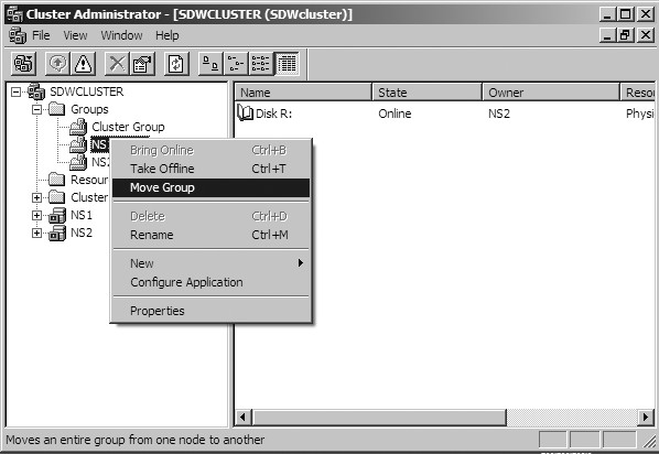
Figure 31 Simulate a failover. (Click on image for enlarged view.)
Congratulations on configuring a virtual cluster. I suggest that you play around and have fun with it. At this point you can load SQL Server 2008 or Exchange Server and begin testing directly from the desktop.
VMware ESX Server 2.0
File System Management on SCSI Disks and RAID
VMFS (VMware ESX Server File System) is a simple, high-performance file system on physical SCSI disks and partitions, used for storing large files such as the virtual disk images for ESX Server virtual machines and, by default, the memory images of suspended virtual machines. The VMFS also stores the redo-log files for virtual machines in nonpersistent, undoable, or append disk modes.
ESX Server 2.0 supports two types of file systems: VMFS version 1 (VMFS-1) or VMFS version 2 (VMFS-2). VMFS-1 is the same VMFS shipped with previous versions of ESX Server 1.x. VMFS-2 is a new VMFS released with ESX Server 2.0 and contains the following features that are not available with the older VMFS-1 file system:
- Ability to span multiple VMFS-2 partitions on the same or different SCSI disks.
- Ability for multiple ESX Servers (and the virtual machines on these servers) to access files on a VMFS-2 volume concurrently (non-clustering setup).
VMware ESX Server 2.0 includes a new automatic per-file locking mechanism that allows these concurrent accesses without file system corruption.
- Larger file system volumes and larger files on the VMFS volumes.
- Raw disks can be mapped as VMFS files.
Note: Unlike VMFS-1, VMFS-2 is not backwardly compatible with previously released (1.x) versions of ESX Server.
A server's VMFS volumes are mounted automatically by the service console, as soon as the storage adapter drivers are loaded, and appear in the /vmfs directory.
The vmkfstools command provides additional functions that are useful when you need to create files of a particular size and when you need to import files from and export files to the service console's file system. In addition, vmkfstools is designed to work with large files, overcoming the 2GB limit of some standard file utilities.
Viewing and Manipulating Files in the /vmfs DirectoryYou can view and manipulate files under /vmfs in these mounted VMFS volumes with ordinary file commands such as ls and cp.
Note: If you use the ls command to view the contents of your /vmfs directory, and the response is slow, then use the /bin/ls command instead.
Although mounted VMFS volumes may appear similar to any other file system such as ext3, VMFS is primarily intended to store large files such as disk images. Unfortunately, the service console (which is based on a Linux 2.4 kernel) does not support files greater than 2GB. nfs is known to run into this limitation, while ftp, scp and cp are not affected by it. Thus, you should use ftp, scp and cp for copying files to and from a VMFS volume, as long as the host file system supports these large files.
Note: If you use the ls command inside a ftp session, the file size may be different from the output of the ls -l command or vmkfstools -l command. This is because ftp uses 32-bit values for file sizes, and the maximum file size it can display is 4GB. However, you can safely transfer any large files between ESX Server machines with a ftp session. The entire file is correctly copied over.
VMFS VolumesIn ESX Server 2.0, a VMFS-2 volume can span multiple partitions, across the same or multiple (up to 32) LUNs or physical disks. A VMFS-2 volume is a logical grouping of physical extents. Each physical extent is part of a disk; for example, a physical disk partition. That is, a physical extent is a disk partition that is part of a VMFS-2 volume.
By contrast, VMFS-1 volumes are limited to a single physical extent.
You can view the VMFS volumes on your ESX Server at any time by changing directories to the /vmfs directory, then listing its contents. You can use vmkfstools -P
# cd /vmfs
# ls
vmhba0:0:0:2 vmhba0:0:0:6
The entries in the /vmfs directory are updated dynamically. Any changes you make to VMFS-2 volumes through the VMware Management Interface are immediately reflected in this directory.
Labelling VMFS VolumesIf you create a VMFS volume on a SCSI disk or partition, you can give a label to that volume and use that label when specifying VMFS files on that volume. For instance, suppose you have a VMFS volume on the SCSI partition vmhba0:3:0:1 and have created a VMFS file nt4.dsk. You can label that volume by using a vmkfstools command such as:
vmkfstools -S mydisk vmhba0:3:0:1
You can then refer to the nt4.dsk file as mydisk:nt4.dsk (instead of vmhba0:3:0:1:nt4.dsk) in a virtual machine configuration file and in other vmkfstools commands. For more information on vmkfstools, see vmkfstools Options.
If there is no persistent binding, then labelling VMFS volumes is especially useful if you may be adding SCSI adapters or disks to your system. The actual disk and target numbers specifying a particular VMFS may change, but the label stays the same. Also, other ESX Servers see the same label, which is useful for LUN ID between servers.
For more information, see Using Persistent Binding.
VMFS AccessibilityThere are two modes for accessing VMFS volumes: public and shared.
- public — This is the default mode for ESX Server.
With a public VMFS version 1 (VMFS-1) volume, multiple ESX Server computers have the ability to access the VMware ESX Server file system, as long as the VMFS volume is on a shared storage system (for example, a VMFS on a storage area network). However, only one ESX Server can access the VMFS volume at a time.
With a public VMFS version 2 (VMFS-2) volumes, multiple ESX Server computers can access the VMware ESX Server file system concurrently. VMware ESX Server file systems with a public mode have automatic locking to ensure file system consistency.
- shared — Used for a VMFS volume that is used for failover-based clustering among virtual machines on the same or different ESX Servers.
Caution: If you create a shared VMFS volume on a LUN, then do not create any additional VFMS volumes on this LUN. Physical bus sharing among clustered virtual machines on a shared VMFS volume interferes with locking mechanisms for other VMFS volumes on the same LUN.
For more information on clustering with ESX Server, see Configuration for Clustering.
Note: In ESX Server 2.0, private VMFS volumes are deprecated. If you have existing VMFS version 1 (VMFS-1) or VMFS version 2 (VMFS-2) private volumes, then you can continue to use them, but we recommend you change the access mode to public. There is no performance penalty in making this change.
VMFS Accessibility on a SANAny VMFS volume on a disk that is on a SAN should have VMFS accessibility set to public or shared. Public, the default and recommended accessibility mode, makes the VMFS volume available to multiple physical servers, and to the virtual machines on those servers. With VMFS-2 volumes, public access is concurrent to multiple physical servers, whereas for VMFS-1 volumes, public access is limited to a single server at a time. For more information on configuring ESX Server with a SAN, see Using Storage Area Networks with ESX Server.
Changing Storage Configuration OptionsTo create or modify disk partitions through the VMware Management Interface, complete the following steps.
- Log in to the VMware Management Interface as root.
The Status Monitor page appears.
- Click the Options tab.
- Click Storage Configuration.
- Make the appropriate changes, then click OK.
Note: You cannot change VMFS accessibility if there are any open files on the VMFS volume. (The attempted operation returns errors). Close any open files, then edit the VMFS volume.
See Configuring Storage: Disk Partitions and File Systems for additional information.
Using vmkfstoolsThe vmkfstools command supports the creation of a VMware ESX Server file system (VMFS) on a SCSI disk. Use vmkfstools to create, manipulate and manage files stored in VMFS volumes. You can store multiple virtual disk images on a single VMFS volume.
Note: You can also do most of the vmkfstools operations through the VMware Management Interface.
vmkfstools Command SyntaxNote: You must be logged in as the root user to run the vmkfstools command.
vmkfstools Syntax When Specifying a SCSI DeviceThe format for the vmkfstools command, when specifying a SCSI device, is:
vmkfstools
where
If
vmhba1:2:0:3
Here, vmhba1 specifies the second SCSI adapter activated by the command vmkload_mod .../XXX.o vmhba. (See VMkernel Module Loader for details on vmkload_mod.) The second number specifies the target on the adapter, the third number specifies the LUN (logical unit number) and the fourth number specifies the partition. Partition 0 (zero) implies the whole disk; otherwise, the number specifies the indicated partition.
The format for the vmkfstools command, when specifying a VMFS volume or file, is:
vmkfstools
where
For example, you can specify a VMFS volume by a path such as:
/vmfs/vmhba1:2:0:3
You can also specify a single VMFS file:
/vmfs/lun1/rh9.dsk
vmkfstools OptionsThis section includes a list of all the options used with the vmkfstools command.
Some of the tasks in this section include options that are suggested for advanced users only. These advanced options are not available through the VMware Management Interface.
Note: The long and short (single letter) forms of options are equivalent. For example, the following commands are identical:
vmkfstools --createfs vmfs2 --blocksize 2m --numfiles 32 vmhba1:3:0:1
vmkfstools -C vmfs2 -b 2m -n 32 vmhba1:3:0:1
If the vmkfstools command fails, and you don't know why, then check the log files in /var/log/vmkernel or use the management interface to view the latest warning.
- Log in to the VMware Management Interface as root.
The Status Monitor page appears.
- Click the Options tab.
The Options page appears.
- Click System Logs.
Basic options are common tasks that you may perform frequently. You may also perform through the management interface.
Creates a VMFS on the specified SCSI device.
-C --createfs [vmfs1|vmfs2]
-b --blocksize #[gGmMkK]
-n --numfiles #
This command creates a VMFS version1 (vmfs1) or version 2 (vmfs2) file system on the specified SCSI device.
For advanced users:
- Specify the block size by using the -b option. The block size must be 2x (a power of 2) and at least 1MB. (The default file block size is 1MB.) You can specify the size in kilobytes, megabytes, or gigabytes by adding a suffix of k (kilobytes), m (megabytes), g (gigabytes) respectively.
- Specify the maximum number of files in the file system with the -n option. The default maximum number of files is 256 files.
Lists the attributes of a VMFS volume or a raw disk mapping.
-P --querypartitions
-P --querypartitions
For a VMFS_volume_name, the listed attributes include the VMFS version number (VMFS-1 or VMFS-2), the number of physical extents (partitions) comprising the specified VMFS volume, the volume label (if any), the UUID (if any), and a listing of the SCSI device names of all the physical extents comprising the VMFS volume.
For a VMFS_volume:fileName, the listed attributes include the vmhba name of the raw disk or partition, corresponding to the mapping referenced by fileName, and any identification information for the raw disk.
Creates a file with the specified size on the file system of the specified SCSI device.
-c --createfile #[gGmMkK]
The size is specified in bytes by default, but you can specify the size in kilobytes, megabytes, or gigabytes by adding a suffix of k (kilobytes), m (megabytes), g (gigabytes) respectively.
Exports the contents of the specified file on the specified SCSI device to a virtual disk on the file system of the service console.
-e --exportfile
After the export, you may transfer the virtual disk to another server machine and import it to a SCSI device on the remote machine.
If your virtual disk has redo logs, you have the following options:
- If you use the exportfile option on the base virtual disk, only the base virtual disk is exported. Any uncommitted redo logs are not exported, but can be copied out separately.
- If you use the exportfile option on a ESX Server redo log, the exported virtual disk contains the redo log, any previously created redo logs, and the base virtual disk. That is, the newly created exported virtual disk appears as if the redo log(s) was committed to its base virtual disk.
Note: However, your original source redo log(s) and base virtual disk remain unchanged.
- If you want to export your redo logs and base virtual disk separately, then use the exportfile option to export the base virtual disk, and the cp command to export each redo log separately.
Use the combination of exportfile and importfile together to copy VMFS files to remote machines. The virtual disk should take less space than the full size of the VMFS file, since the virtual disk does not include zeroed sectors of the VMFS file.
Imports the contents of a VMware virtual, plain, or raw disk on the service console to the specified file on the specified SCSI device.
-i --importfile
This command is often used to import the contents of a VMware Workstation or VMware GSX Server virtual disk onto a SCSI device. You may also run this command to import a virtual disk, that was created by exporting the contents of a disk from another SCSI device.
Note: The destination device must have space for the entire size of the virtual disk, even if it is mostly free space, as the complete contents of the source disk are copied.
Lists the files on the file system on the specified device.
-l --list
-h --human-readable
-M --verbosemappings
The output includes permissions, sizes and the last modification time for redo logs, virtual disk files, and swap files. You can use the -h option to print the sizes in an easier-to-read format; for example, 5KB 12.1MB, and so on.
(Advanced users only) The -M option lists the vmhba name that corresponds to each raw disk mapping.
Sets the name of the VMFS on the specified SCSI device to
-S --setfsname
You can see the VMFS name by running the vmkfstools command with the -l option, vmkfstools -l.
Advanced vmkfstools OptionsAdvanced options are tasks that you may perform infrequently. These tasks are not available through the management interface, or are available in a limited form, and are suggested for advanced users only.
Commits the redo log of the specified file, making the associated changes permanent.
-m --commit
If a virtual machine is in undoable or append mode, then the redo log is created automatically. The name of the redo log is derived by appending .REDO to the name of the file that contains the base disk image. You can commit the changes to the disk that are stored in the redo log by using the commit option or eliminate the changes by using the rm command to delete the redo-log file.
Sets the VMFS on the specified SCSI device to the specified mode.
-F --config [public|shared|writable]
Note: In ESX Server 2.0, private VMFS volumes are deprecated. If you have existing VMFS version 1 (VMFS-1) or VMFS version 2 (VMFS-2) private volumes, then change the access to public.
Public —With public VMFS-2 volumes, multiple ESX Server computers can access the same VMware ESX Server VMFS volume concurrently. VMware ESX Server file systems with a public access mode use an automatic per-file locking to ensure file system consistency.
With a public VMFS-1 volume, multiple ESX Server computers have the ability to access the VMware ESX Server VMFS volume, as long as the VMFS volume is on a shared storage system (for example, a VMFS on a storage area network). However, only one ESX Server can access the VMFS-1 volume at a time.
Note: ESX Server creates VMFS volumes as public by default.
Shared —The shared access mode allows virtual machines on multiple servers to access the same virtual disk on a VMFS-2 volume simultaneously. (In public mode, virtual machines can only access the same VMFS volume, never the same virtual disk, at the same time.)
Note: A VMFS volume that is used for failover-based clustering should have its mode set to shared.
Writable —When virtual machines access a file on a shared VMFS, the file system metadata becomes read-only. That is, no virtual machine or user command can create, delete or change the attributes of a file.
If you need to create, remove, or change the length of a file (vmkfstools -X), then you need to change the volume to "writable". First, be sure that no virtual machines are accessing the VMFS volume (all virtual machines are powered off or suspended), then change the file system metadata to writable with the command, vmkfstools --config writable. Once you power on or resume a virtual machine, the file system metadata reverts to being read-only.
Prints out the name of a Linux device that represents the specified SCSI device on the service console.
-N --consolename
You can use the resulting device name to access the SCSI device by using commands such as fdisk on the service console. The association between the Linux device name and the specified SCSI device lasts only until ESX Server is unloaded or the server machine is rebooted.
Extends an existing logical VMFS-2 volume by spanning multiple partitions.
-Z --extendfs
-n --numfiles #
This option adds another physical extent (designated by
Note: A logical VMFS-2 volume can have at most 32 physical extents.
This operation is not supported on the VMFS-1 file system and in fact, returns an error if the specified SCSI device is formatted as VMFS-1. Each time you use this option and extend a VMFS-2 volume with a physical extent, the VMFS volume supports, by default, an additional 64 files. You can change this default number of files by using the -n option.
Maps a raw disk or partition to a file on a VMFS-2 volume.
-r --maprawdisk
Once this mapping is established, you can access the raw disk like a normal VMFS file. The file length of the mapping is the same as the size of the raw disk or partition. The mapping can be queried for the raw SCSI device name by using the -P option.
By mapping a raw disk or partition to a file, you can manipulate this raw disk or partition as any other file. In addition, this mapping enables you to have undoable, append, and nonpersistent "raw disks".
All VMFS-2 file-locking mechanisms apply to raw disks.
Displays disk geometry for a VMware Workstation or GSX Server virtual disk.
-g -- geometry
The output is in the form: Geometry information C/H/S is 1023/128/32, where C represents the number of cylinders, H represents the number of heads, and S represents the number of sectors.
When importing VMware Workstation or VMware GSX virtual disks to VMware ESX Server, you may see a disk geometry mismatch error message. A disk geometry mismatch may also be the cause if you have problems loading a guest operating system, or running a newly created virtual machine.
View the events log through the VMware Management Interface (Users and Events page for the virtual machine) or through the service console (the vmware.log file, found, by default, in the
If the disk geometry information is different, then specify the correct information, from the output of the vmkfstools -g command, in the configuration file of the newly created virtual machine.
See Problems Importing GSX Server Virtual Machines to ESX Server for complete details on specifying the disk geometry in a virtual machine's configuration file.
Extends the specified VMFS to the specified length.
-X --extendfile #[gGmMkK]
Use this command to extend the size of a disk allocated to a virtual machine, after the virtual machine has been created. The virtual machine that uses this disk file must be powered off when you enter this command. Also, the guest operating system must be able to recognize and use the new size of the disk, for example by updating the file system on the disk to take advantage of the extra space.
You specify the size in kilobytes, megabytes, or gigabytes by adding a suffix of k (kilobytes), m (megabytes), g (gigabytes) respectively.
Manages SCSI reservations of physical targets or LUNs.
-L --lock [reserve|release|reset]
Caution: Be careful when using these commands. The reserve, release, and reset commands can interrupt the operations of other servers on a storage area network (SAN), so use these commands with great caution.
The -L reserve command reserves the specified raw disk, or the disk containing the specified VMFS volume. After the reservation, other servers will get a SCSI reservation error if they attempt to access that disk, but the server that did the reservation will be able to access the disk normally.
The -L release command releases the reservation on the specified disk, or disk containing the specified VMFS volume. Any other server can access the disk again.
The -L reset command does a SCSI reset to the specified disk. Any reservation held by another server is released.
Recovers a VMFS.
-R --recover
This command enables you to recover a VMFS (accessible by multiple ESX servers) when other vmkfstools commands indicate that the file system is locked by another ESX Server machine, but, in fact, no other server is currently accessing this file system. This situation may occur if the VMFS was being accessed by a server (for example, running a virtual machine) and that server crashed.
Note: You should only use this command if you are certain that no other ESX Server is still accessing the file system.
Scans the specified vmhba adapter for devices and LUNs.
-s --scan
This option is particularly useful for adapters connected to storage area networks, particularly if you are reconfiguring your SAN. If a new device or LUN becomes accessible through the adapter, then ESX Server registers this new virtual device for use by virtual machines. If an existing device or LUN is no longer used and appears to be gone, then it is removed from use by virtual machines.
Note: Only use this -s option for Fibre Channel adapters.
You can see the results of the scan by using ls /vmfs or looking at the contents of /proc/vmware/scsi.
Creates a swap file with the specified size on the VMFS volume of the specified SCSI device.
-w --createswapfile #[gGmMkK]
The size is specified in bytes by default, but you can specify the size in kilobytes, megabytes, or gigabytes by adding a suffix of k (kilobytes), m (megabytes), g (gigabytes) respectively.
ESX Server starts using the swap file immediately after it is created.
You can use the -w option to activate an existing swap file. If the newly specified length of the swap file is different from the length of the existing swap file, then the length of the swap file is changed.
Caution: If you reboot the ESX Server machine, ESX Server does not recognize the file as a swap file until you activate it as mentioned previously.
Changes the VMFS from VMFS-1 to VMFS-2.
-T --tovmfs2
This command converts the VMFS volume on the specified partitions from VMFS-1 to VMFS-2, while preserving all files in the volume. ESX Server's locking mechanism attempts to ensure that no remote ESX Server or local process is accessing the VMFS volume that is being converted.
Note: If you have an active swap partition, you must deactivate it before running this command. Deactivate swap through the VMware Management Interface and reboot your server. Once this vmkfstools -T command completes, you can reactivate your swap file.
This conversion may take several minutes. When your prompt returns, the conversion is complete.
Note: In ESX Server 2.0, private VMFS volumes are deprecated. If you have an existing VMFS version 1 (VMFS-1) private volume, then the newly created VMFS-2 volume's access mode is automatically changed to public.
Before starting this conversion, check the following:
- Back up the VMFS-1 volume that is being converted
- Be sure there are no virtual machines powered on using this VMFS-1 volume
- (SAN only) Be sure no other ESX Server is accessing this VMFS-1 volume
- (SAN only) Be sure this VMFS-1 volume is not mounted on any other ESX Server
Caution: The VMFS- 1 to VMFS-2 conversion is a one-way process. Once the VMFS volume is converted to VMFS-2, you cannot revert it back to a VMFS-1 volume.
Note: The first time you access a newly converted VMFS-2 volume, the initial access will be slow, because of internal volume consistency checking.
Examples Using vmkfstoolsThis section includes examples using the vmkfstools command with the different options described previously.
Create a new file system.
vmkfstools -C vmfs2 -b 2m -n 32 vmhba1:3:0:1
This example illustrates creating a new VMFS version 2 (vmfs2) on the first partition of target 3, LUN 0 of SCSI adapter 1. The file block size is 2MB and the maximum number of files is 32.
Extends the new logical volume by spanning two partitions.
vmkfstools -Z vmhba0:1:2:4 vmhba1:3:0:1
This example illustrates extending the new logical file system by adding the 4th partition of target 1 (and LUN 2) of vmhba adapter 0. The extended file system supports a maximum of 64 (2 X 32) files, and spans two partitions — vmhba1:3:0:1 and vmhba0:1:2:4.
You can address the file system by using the name of its head partition; for example, vmhba1:3:0:1.
Names a VMFS volume.
vmkfstools -S mydisk vmhba1:3:0:1
This example illustrates assigning the name of mydisk to the new file system.
Creates a new VMFS virtual disk file.
vmkfstools -c 2000m mydisk:rh6.2.dsk
This example illustrates creating a 2GB VMFS file with the name of rh6.2.dsk on the VMFS volume named mydisk. The rh6.2.dsk file represents an empty disk that may be accessed by a virtual machine.
Imports the contents of a virtual disk to the specified file on a SCSI device.
vmkfstools -i ~/vms/nt4.dsk vmhba0:2:0:0:nt4.dsk
The example illustrates importing the contents of a virtual disk (that contains Windows NT 4.0) from the service console's file system to a file named nt4.dsk on target 2 of SCSI adapter 0.
You can configure a virtual machine to use this virtual disk by adding the following lines to its configuration file:
scsi0.virtualDev = vmxbuslogic
scsi0:0.present = TRUE
scsi0:0.name = vmhba0:2:0:0:nt4.dsk
Migrate virtual machines to VMware GSX Server or VMware Workstation, then back to VMware ESX Server.
Note: The following example, illustrating the -e and -i options, result in the export or import of a virtual disk.
This example illustrates migrating a virtual machine's virtual disk file from ESX Server to VMware GSX Server or VMware Workstation, then migrating the virtual disk back to ESX Server.
vmkfstools -e winXP.vmdk vmhba0:6:0:1:winXP.dsk
The preceding command exports the winXP.dsk virtual disk file to one or more .vmdk files, maximum size 2GB, that you can use as a virtual disk in a virtual machine on GSX Server or Workstation. The resultant winXP.vmdk file(s) can reside on a VMFS volume, or an /ext2, /ext3, or NFS file system.
The following example imports a GSX Server or Workstation virtual disk file into the VMFS volume on the specified SCSI device.
vmkfstools -i winXP.vmdk vmhba0:6:0:1:winXP.dsk
By contrast, if you are importing directly into a raw partition, the example becomes:
vmkfstools -i winXP.vmdk vmhba0:6:0:1
Lists the files on the VMFS of the specified device.
vmkfstools -l vmhba0:2:0:0
This command illustrates listing the contents of the file system, including redo logs, virtual disk files, and swap files on target 2 of SCSI adapter 0.
Scans a vmhba adapter.
This example illustrates scanning the vmhba1 adapter for any new or removed targets or LUNs.
vmkfstools -s vmhba1
Accessing Raw SCSI DisksYou can access raw disks directly or use the vmkfstools -r command to map them to files on VMFS-2 volumes. Once this mapping is established, you access the raw disk or partition like a normal file. For more information on this mapping, see Using vmkfstools, in particular, the vmkfstools -r option.
Using a Physical Disk in a Virtual MachineIn order for the virtual machine to access a physical disk or LUN, you must add the disk to the virtual machine. This example assumes that the virtual machine's first disk is a virtual disk and you are adding the physical disk as the second disk.
If you want the virtual machine's first disk to be a physical disk, see Creating a New Virtual Machine and select System LUN/Disk for your virtual disk.
- Log into the VMware Management Interface as the user who owns the virtual machine or as the root user.
The Status Monitor page appears.
- Click the arrow to the right of the terminal icon (
) for the virtual machine you want to change and choose Configure Hardware.
The Hardware page for this virtual machine appears in a new browser window.
- Click Add Device. The Add Device Wizard starts.
- Click Hard Disk. The Virtual Disk Type page appears.
- Click System LUN/Disk to allow the virtual machine to access a physical disk stored on a LUN. Then specify the following.
- Choose the LUN you want to use in the Storage Controller LUN list.
- Specify the virtual device node. Select the appropriate SCSI ID in the Virtual SCSI Node list.
- Click OK to add the disk.


In order to assign SCSI disks to a virtual machine, you need to know which controller the drive is on and what the SCSI target ID of the controller is. This section helps you determine these values without opening your computer and physically looking at the SCSI target ID settings on the drives.
SCSI disks may be accessed by local SCSI adapters, or on a SAN by Fibre Channel adapters. Therefore, whenever we describe SCSI adapters in this section, these descriptions also apply to Fibre Channel adapters, even though they are not explicitly mentioned.
On a standard Linux system, or for a VMware service console that has SCSI or Fibre Channel (FC) controllers assigned to the service console rather than the VMkernel, information on attached SCSI devices, including SCSI target IDs is available in the boot log (usually /var/log/messages), or from examining /proc/scsi/scsi.
Information about the SCSI controllers assigned to the VMkernel and about the devices attached to these controllers is available in the /proc/vmware/scsi directory once the VMkernel and the VMkernel device module(s) for the SCSI controller(s) have been loaded.
Each entry in the /proc/vmware/scsi directory corresponds to a SCSI controller assigned to the VMkernel. For example, assume you issued a vmkload_mod command with the base name vmhba and a single SCSI controller was found.
To identify the controller, type this command:
ls -l /proc/vmware/scsi
The output of the ls command is:
total 0
dr-xr-xr-x 2 root ���root������ 0 Jun 22 12:44 vmhba0
Each SCSI controller's subdirectory contains entries for the SCSI devices on that controller, numbered by SCSI target ID and LUN (logical unit number). Run cat on each target ID:LUN pair to get information about the device with that target ID and LUN. For example, type this command:
cat /proc/vmware/scsi/vmhba0/1:0
The following information is displayed:
Vendor: SEAGATE Model: ST39103LW Rev: 0002
Type: Direct-Access ANSI SCSI revision: 02
Size: 8683 Mbytes
Queue Depth: 28
Partition Info:
Block size: 512
Num Blocks: 17783240
�����num: Start ��� Size Type
�����4: ��1 �17526914 fb
Partition 0:
����VM 11
����Commands 2
����Kbytes read 0
����Kbytes written 0
����Commands aborted 0
����Bus resets 0
Partition 4:
����Commands 336
����Kbytes read 857
����Kbytes written 488
����Commands aborted 0
����Bus resets 0
This information should help you determine the SCSI target ID to use in the storage configuration page, as displayed by the VMware Management Interface. See Configuring Storage: Disk Partitions and File Systems.
Sharing the SCSI Bus Normally, VMware ESX Server enforces locking and does not allow two virtual machines to access the same virtual disk (VMFS file) at the same time. If a second virtual machine tries to access a VMFS file, it gets an error and does not power on. However, it is often useful to have more than one virtual machine share a disk in order to provide high availability. This configuration is commonly used for disk-based failover, in which one machine takes over running an application when the primary machine fails. The data required for the application is typically stored on a shared disk, so the backup machine can immediately access the necessary data when the failover occurs. See Configuration for Clustering for complete information on clustering with ESX Server. The bus sharing setting is used to determine if virtual machines are allowed to access the same virtual disk simultaneously. Use the VMware Management Interface to change the bus sharing settings for each virtual machine that will access the same virtual disk simultaneously. There are three bus sharing options. To enable sharing of virtual disks, choose Virtual or Physical. All virtual disks on the specified virtual bus will be sharable and have the specified mode. If the bus sharing is Virtual, only virtual machines on the same physical machine will be able to share disks. This setting allows for a "cluster-in-a-box" configuration, in which all members of a high-availability cluster are on the same physical machine. This setup is useful for providing high availability when the likely failures are due to software or administrative errors. If the bus sharing is Physical, virtual machines on different physical machines will be able to share disks. In this case, the VMFS holding the virtual disks must be on a physically shared disk, so all of the physical machines can access it. This setup is useful for providing high availability when the likely failures also include hardware errors. When a shared disk is used for high availability purposes, the current machine that is running the application and using the shared data often reserves the disk using a SCSI command. Also, if the bus sharing is Physical, commands that reserve, reset or release a shared virtual disk are transmitted through to the physical disk, so other machines sharing the disk can properly detect when a virtual disk has been reserved or reset. Therefore, when you are sharing disks among virtual machines across physical machines for high availability purposes, it is often best to put only a single VMFS with a single virtual disk on each shared disk — that is, have only one virtual disk per physical disk. In such a configuration, each virtual disk can be reserved and released independently. To change the bus sharing setting, complete the following steps:
VMware ESX Server can be used effectively with storage area networks (SANs). ESX Server supports Qlogic and Emulex host bus adapters, which allow an ESX Server computer to be connected to a SAN and to see the disk arrays on the SAN.
The SCSI configuration information contained in this section also applies to Fibre Channel adapters, but note that FC adapters may require additional configuration as well.
For information on supported SAN hardware, download the VMware ESX Server SAN Compatibility List from the VMware Web site at www.vmware.com/support/esx2.
Understanding Storage ArraysLarge storage systems (also known as disk arrays) combine numerous disks into arrays for availability and performance. Typically, a collection of disks is grouped into a Redundant Array of Inexpensive Disks (RAID) array to protect the data by eliminating disk drives as a potential single point of failure.
Disk arrays carve the storage RAID set into logical units (LUNs) that are presented to the server in a manner similar to an independent single disk. Typically, LUNs are few in number, relatively large, and fixed in size.
You can create LUNs with the storage management application of your disk array.
Installing ESX Server with Attached SANsWe recommend that you install ESX Server software on a local SCSI disk.
Caution: Be sure that all Fibre Channel adapters (QLogic or Emulex) are detached from the SAN during ESX Server installation. If they are not disconnected, SAN disks are often displayed first in the list of drives displayed during installation. This may cause confusion when the service console is being installed.
In addition, we recommend that all Fibre Channel adapters are dedicated exclusively for the virtual machines. Even though these FC adapters are dedicated to virtual machines, the LUNs on the SANs are visible to system management agents on the service console.
Configuring VMFS Volumes on SANsBe sure that only one ESX Server has access to the SAN while you are using the VMware Management Interface to configure the SAN and format the VMFS-2 volumes. After you have finished the configuration, be sure that all partitions on the physically shared SAN disk are set for public or shared access for access by multiple ESX Servers (see VMFS Accessibility).
For information on configuring SANs, scanning for LUNs and setting persistent bindings through the VMware Management Interface, see Configuring a Swap File.
Scanning for Devices and LUNsESX Server scans for devices, and LUNs on these devices, whenever a Fibre Channel driver is loaded. You can manually initiate a scan through the VMware Management Interface or by using the vmkfstools -s command.
You may want to rescan devices or LUNs whenever you add a new disk array to the SAN or create new LUNs on a disk array. You may also want to rescan LUNs when you change the LUN masking on a disk array.
Note: For QLogic adapters, you must do one additional step before scanning, in order to recognize new LUNs on existing disk arrays. For each and every numeric entries in /proc/scsi/qla2200 or /proc/scsi/qla2300, run the appropriate command, as the root user, on the service console:
echo "scsi-qlascan" > /proc/scsi/qla2200/
or
echo "scsi-qlascan" > /proc/scsi/qla2300/
These commands tell the QLogic driver to clear its cache of existing LUNs.
Caution: Do not run the vmkfstools -s command on non-Fibre Channel adapters.
Type the following command to scan for devices or LUNs through a particular FC SCSI adapter:
vmkfstools -s
For example, if you wanted to rescan SCSI adapter vmhba0 for new (and removed) devices or LUNs, type:
vmkfstools -s vmhba0
For more information on using vmkfstools, see Using vmkfstools.
Note: If you are using multipathing with multiple FC HBAs, then you should run this command on all of the FC HBAs. If, after your rescan, you see new LUNs and they have VMFS volumes, then you will see the appropriate subdirectories when you view the contents of the /vmfs directory.
Choosing QLogic AdaptersIf you are using a QLogic storage adapter, then be sure to choose the right driver version:
- IBM storage — QLogic driver version 6.04 (default)
- HP storage — QLogic driver version 6.04 (default)
- EMC storage — QLogic driver version 6.04 (default)
In order to use all storage devices on your SAN, you may need to change some VMkernel configuration options as described below.
To make these changes, complete the following steps.
- Log in to the VMware Management Interface as root.
The Status Monitor page appears.
- Click the Options tab.
- Click Advanced Settings.
- To change an option, click the current value, then enter the new value in the dialog box and click OK.
For more information on changing these settings, see Changing Advanced Settings.
By default, the VMkernel scans for only LUN 0 to LUN 7 for every target. If you are using LUN numbers larger than 7 you must change the setting for the DiskMaxLUN field from the default of 8 to the value that you need. For example, if you now have LUN numbers 0 to 15 active, set this option to 16. Currently, an ESX Server machine can see a maximum of 128 LUNs over all disk arrays on a SAN.
By default, the VMkernel is configured to support sparse LUNs — that is, a case where some LUNs in the range 0 to N-1are not present, but LUN N is present. If you do not need to use such a configuration, you can change the DiskSupportSparseLUN field to 0. This change decreases the time needed to scan for LUNs.
The DiskMaskLUNs configuration option allows the masking of specific LUNs on specific HBAs. Masked LUNs are not touched or accessible by the VMkernel, even during initial scanning. The DiskMaskLUNs option takes a string comprised of the adapter name, target ID and comma-separated range list of LUNs to mask. The format is as follows:
For example, you want to mask LUNs 4, 12, and 54-65 on vmhba 1 target 5, and LUNs 3-12, 15, and 17-19 on vmhba 3 target 2. To accomplish this, set the DiskMaskLUNs option to the following:
"vmhba1:5:4,12,54-65;vmhba3:2:3-12,15,17-19;"
Note: LUN 0 cannot be masked.
The DiskMaskLUNs option subsumes the DiskMaxLUN option for adapters that have a LUN mask. In other words, continuing the preceding example, there are four adapters, vmhba0, vmhba1, vmhba2, and vmhba3, and the DiskMaxLUN option is set to 8. In this example, vmhba0 and vmhba2 only scan LUNs 0-7, but vmhba1 and vmhba3 scan all LUNs that are not masked, up to LUN 255, or the maximum LUN setting reported by the adapter, whichever is less.
For administrative or security purposes, you can use LUN masking to prevent the server from seeing LUNs that it doesn't need to access. Refer to your documentation on disk arrays for more information.
Using IBM FAStT Disk ArraysAn IBM FAStT disk array sometimes returns vendor-specific status codes that ESX Server interprets as errors. These status codes are temporary -- indicating, for example, that the firmware has been upgraded or that the battery for the disk cache needs to be charged. ESX Server, in its default configuration, may interpret these status codes to mean that a LUN exists but is not accessible.
You avoid this problem by using a special ESX Server 2.0 configuration option. Log in to the management interface as the root user, click Advanced Settings, then click VMkernel Configuration. Find the option DiskRetryUnitAttention and be sure that it is enabled (the default).
With this option enabled, ESX Server automatically retries SCSI commands when these vendor-specific status codes are received.
Troubleshooting SAN Issues with ESX Server You can view LUNs through the VMware Management Interface or viewing the output of ls /proc/vmware/scsi/
- DiskMaxLUN — the maximum number of LUNs per vmhba that are scanned by ESX Server.
You can view and set this option through the VMware Management Interface (Advanced Settings in the Options page) or by viewing this setting through/proc/vmware/config.
- DiskSupportSparseLUN — if this option is on, then ESX Server scans past any missing LUNs. If this option is off, ESX Server stops scanning for LUNs if any LUN is missing.
You can view and set this option through the VMware Management Interface (Advanced Settings in the Options page) or by viewing this setting through/proc/vmware/config.
- LUN masking — With LUN masking, each LUN is exclusively assigned and accessed by a specific list of connections. Be sure that LUN masking is implemented properly and that the LUNs are visible to the HBAs on ESX Server.
- Zoning — Zoning limits access to specific storage devices and increases security and decreases traffic over the network. If you use zoning, be sure that zoning on the SAN switch is set up properly and that all vmhba and the controllers of the disk array are in the same zone.
- Storage controller — If a disk array has more than one storage controller, then make sure that the SAN switch has a connection to the controller that owns the LUNs you wish to access. On some disk arrays, only one controller is "active" and the other controller is "passive" until there is a failure. If you are connected to the wrong controller, then you may not see the expected LUNs, or you may see the LUNs, but may get errors when trying to access them.
You can specify persistent bindings for your Fibre Channel host bus adapters (HBAs). With persistent binding, ESX Server assigns specific target IDs to specific Fibre Channel SCSI devices. This target ID association is retained from reboot to reboot unless changed by you.
Persistent binding is particularly useful if you are using raw disks with ESX Server. A raw disk is directly mapped to a LUN or physical disk drive on your storage area network (SAN). ESX Server directly accesses the data on this disk as a raw device (and not as a file on a VMFS volume).
You can persist bindings through the VMware Management Interface or through the service console. For complete information on persisting bindings through the management interface, see Configuring a Swap File.
Determining Target IDs through the Service Console If you prefer to use the service console, type cat /proc/scsi/
#cat /proc/scsi/
.
.
.
Portname: 10:00:00:00:c9:32:23:49 Nodename: 20:00:00:00:c9:32:23:49
Link Up - Ready:
PortID 0x21900
Fabric
Current speed 1G
lpfc0t00 DID 021500 WWPN 20:00:00:60:16:3c:ad:13 WWNN 20:00:00:60:16:3c:ad:13
where:
Portname: 10:00:00:00:c9:32:23:49 | Adapter port name |
Nodename: 20:00:00:00:c9:32:23:49 | Adapter node name |
lpfc0t00 | 0 (lpfc0) is the host bus adapter and 00 is the target |
WWPN 20:00:00:60:16:3c:ad:13 | Target world wide port name (WWPN) |
WWNN 20:00:00:60:16:3c:ad:13 | Target world wide node name (WWNN) |
#cat /proc/scsi/
.
.
.
SCSI Device Information:
scsi-qla0-adapter-node=200100e08b229b53;
scsi-qla0-adapter-port=210100e08b229b53;
scsi-qla0-target-0=20000060163cad13;
.
.
.
where:
200100e08b229b53 | Adapter world wide port name (adapter-port) |
210100e08b229b53 | Adapter world wide node name (adapter-node) |
qla0 | 0 is the host bus adapter |
target-0 | 0 is the target |
20000060163cad13 | World wide port name |
The pbind.pl script is located in the /usr/sbin directory. As root, type pbind.pl to see the list of options for this command.
pbind.pl Option | Description |
|---|---|
pbind.pl -A | Persists bindings for all adapters. |
pbind.pl -D | Deletes bindings for all adapters. |
pbind.pl -a | Adds bindings for all adapters specified in |
pbind.pl -d | Deletes bindings for all adapters specified in |
pbind.pl -r | Shows you the result without actually making any change. |
pbind.pl -s | Displays supported adapters and their paths. |
pbind.pl -q | Quiet mode; suppresses normal status output. |
This example adds bindings for all QLogic 2200 hosts.
pbind.pl -a /proc/scsi/qla2200/
This example adds binding for QLogic 2200 host 2.
pbind.pl -a /proc/scsi/qla2200/2
Note: Typing a wildcard character, for example, pbind.pl -a /proc/scsi/qla2200/* is invalid.
Using Multipathing in ESX ServerESX Server 2.0 includes multipathing support to maintain a constant connection between the server machine and the storage device in case of the failure of a host bus adapter (HBA), switch, storage controller (or storage processor; abbreviated as SP in the following diagram), or a Fibre Channel cable. Unlike previous versions of ESX Server, this version of multipathing support does not require specific failover drivers.

In the preceding diagram, there are multiple, redundant paths from each server to the storage device. For example, if HBA1, or the link between HBA1 and the Fibre Channel (FC) switch breaks, HBA2 takes over and provides the connection between the server and the switch. This process is called HBA failover.
Similarly, if SP1, or the link between SP1 and the switch breaks, SP2 takes over and provides the connection between the switch and the storage device. This process is called SP failover. VMware ESX Server 2.0 provides both HBA and SP failover with its multipathing feature. (SP failover may not be supported by all disk arrays.)
For information on supported SAN hardware, download the VMware ESX Server SAN Compatibility List from the VMware Web site at www.vmware.com/support/esx2.
Viewing the Current Multipathing StateYou can view the current multipathing state by examining the proc entries for each of your LUNs. Each LUN is represented by one proc entry, represented by its canonical name.
The canonical name for a LUN is the first path ESX Server finds to the LUN. Since ESX Server begins its scans at the first HBA and the lowest device number, the first path (and also the LUN's canonical name) is the path with the lowest number HBA and device number. For example, if the paths to a LUN are vmhba0:0:2, vmhba1:0:2, vmhba0:1:2 and vmhba1:1:2, then the LUN's canonical name is vmhba0:0:2.
- Change directories to the SCSI adapter, /proc/vmware/scsi/
and view the directory listing. cd /proc/vmware/scsi/vmhba0
lsThe output resembles the following:
0:0 0:2 stats
- View the proc entry for a LUN.
Each entry includes the partition table, statistics, the vendor ID, the size of the disk, and so on. The list of path(s) to the LUN is included at the end of the entry. For example, the entry for /proc/vmware/scsi/vmhba0/0:2 includes:
Vendor: IBM Model: 2105E20 Rev: .100
Type: Direct-Access ANSI SCSI revision: 03
Size: 17166 Mbytes
Queue Depth: 16
Partition Info:
Block size: 512
Num Blocks: 35156288cmds reads KBread writes KBwritten cmdsAbrt busRst
18 11 7 0 0 0 0
paeCmds paeCopies splitCmds splitCopies issueAvg totalAvg
0 0 0 0 14557 572198
.
.
.Paths:fixed
vmhba0:0:2 on*#
vmhba1:0:2 on
vmhba0:1:2 on
vmhba1:1:2 on
Active: 0 Queued: 0
LUN vmhba0:0:2 has a "fixed" policy. There are four paths to this LUN; the first path listed is always the canonical name for the LUN. The list of paths indicates the different ways that the LUN can be accessed. For example, the presence of path vmhba1:1:2 indicates that one of the ways to access the LUN is at device 1 via HBA 1.
The asterisk (*) indicates that the first path, vmhba0:0:2 is the current, active path and the pound (#) indicates that this is the preferred path from the server to the LUN. (By default, the preferred path for a LUN is its canonical name.)
The status of each path to the LUN is indicated by on, off, or dead. The on status indicates that the path is OK, and data is being transferred successfully. The off status indicates that this path has been deliberately turned off, while dead indicates that the path should be active, but the software cannot connect to the LUN through this path.
You can specify the default policy for the multipathing feature. There are two policies:
- fixed — ESX Server always uses the preferred path to the LUN; if it cannot access the LUN through the preferred path, then it tries the alternate paths. Fixed is the default policy in ESX Server.
Type the following command to select the fixed policy for a LUN, in this example, vmhba0:0:0.
echo "policy fixed" > /proc/vmware/scsi/vmhba0/0:0
- mru — ESX Server uses the most recent path to the LUN until this path becomes unavailable. That is, ESX Server does not automatically revert back to the preferred path.
Type the following command to select the mru policy for a LUN, in this example, vmhba0:0:0.
echo "policy mru" > /proc/vmware/scsi/vmhba0/0:0
Note: You can select a different policy for each LUN.
Specifying PathsYou can use the proc command to disable and enable paths, set the active path, and set the preferred path, as illustrated in the following examples.
Disabling a PathType the following command to disallow the specified path to the LUN.
echo "pathoff
In this example, you are changing the status of path vmhba1:0:1 to off in the proc entry for LUN vmhba0:0:1.
echo "pathoff vmhba1:0:1" > /proc/vmware/scsi/vmhba0/0:1
Enabling a PathType the following command to enable the specified path to the LUN.
echo "pathon
In this example, you are changing the status of path vmhba1:0:1 to on in the proc entry for LUN vmhba0:0:1.
echo "pathon vmhba1:0:1" > /proc/vmware/scsi/vmhba0/0:1
Setting the Preferred PathType the following command to set the specified path as the preferred path to the LUN.
echo "preferred
In this example, you are making path vmhba1:0:1 the preferred path (indicated by #) in the proc entry for LUN vmhba0:0:1.
echo "preferred vmhba1:0:1" > /proc/vmware/scsi/vmhba0/0:1
Saving Your Multipathing SettingsYour multipathing settings are saved when shutting down ESX Server normally. However, we suggest you run the following command, as root, to ensure your settings are saved, in case of an abnormal shutdown.
su
# /usr/sbin/vmkmultipath -S
By running this command, your multipathing settings are restored automatically on bootup.
In Case of FailoverWhen a cable is pulled, I/O freezes for approximately 30-60 seconds, until the SAN driver determines that the link is down, and failover occurs. During that time, the virtual machines (with their virtual disks installed on a SAN) may appear unresponsive, and any operations on the /vmfs directory may appear to hang. After the failover occurs, I/O should resume normally.
Even though ESX Server's failover feature ensures high availability and prevents connection loss to SAN devices, all connections to SAN devices may be lost due to disastrous events, that include multiple breakages.
If all connections to the storage device are not working, then the virtual machines will begin to encounter I/O errors on their virtual SCSI disks. Also, operations in the /vmfs directory may eventually fail after reporting an "I/O error".
Settings for QLogic AdaptersFor QLogic cards, you may want to adjust the PortDownRetryCount value in the QLogic BIOS. This value determines how quickly a failover occurs when a link goes down.
If the PortDownRetryCount value is
For more information on changing the PortDownRetryCount value, refer to your QLogic documentation.
Failover in Windows 2000 and Windows Server 2003 Guest Operating SystemsFor the Windows 2000 and Windows Server 2003 guest operating systems, you may want to increase the standard disk TimeOutValue so that Windows will not be extensively disrupted during failover.
- Select Start > Run, type regedit.exe, and click OK.
- In the left panel hierarchy view, double-click HKEY_LOCAL_MACHINE, System, CurrentControlSet, Services, then Disk.
- Select the TimeOutValue and set the Data value to x03c (hexadecimal) or 60 (decimal). By making this change, Windows waits at least 60 seconds, for delayed disk operations to complete, before generating errors.
- Click OK and exit the Registry Editor program.
Clustering is simply described as providing a service via a group of servers to get high availability, scalability or both
For example, all nodes in a cluster serve a Web site that serves static content. The main gateway distributes requests to all nodes according to load. It redirects requests to remaining nodes if one crashes. This gives better availability and better performance. Network Load Balancing in Windows 200 provides such a service.
Another example of a more complex configuration: A single node serves a database. If that node crashes, the clustering software must restart the database on another node. The database application knows how to recover from a crash. In normal operation, other nodes are used for running other applications. Microsoft Cluster Service and Veritas Cluster Service provide such a service.
Applications that Can Use ClusteringTo take advantage of clustering services, applications need to be clustering aware.
Such applications can be:
- Stateless, as Web servers and VPN servers are.
- With built-in recovery features, like those in database servers, mail servers, file servers or print servers.
Available clustering software include:
- Microsoft Clustering Service (MSCS)
Provides fail-over support for 2- to 8-node clusters for applications such as databases, file servers and mail servers
- Microsoft Network Load Balancing (NLB)
Load balances incoming IP traffic across a cluster of nodes for applications such as Web servers and terminal services.
- Veritas Clustering Service (VCS)
A typical clustering setup includes:
- Disks that are shared between nodes
These are needed if the application uses dynamic data as mail servers or database servers do.
The shared disks may be shared SCSI disks or a storage area network using Fibre Channel.
- Extra network connectivity between nodes for monitoring heartbeat status.
- A method for redirecting incoming requests.
Network Load Balancing, Microsoft Clustering Service and Veritas Clustering Service run without modification in virtual machines on ESX Server 2.0.
Use of clustering services in virtual machines provides high availability with less hardware (such as machines and network adapters).
Clustering ScenariosSeveral scenarios are possible for clustering in virtual machines.
Cluster in a Box —This provides simple clustering to deal with software crashes or administrative errors. The cluster consists of multiple virtual machines on a single physical machine. It supports shared disks without any shared SCSI hardware. It supports heartbeat network without any extra network adapters.

A four-node cluster on a single physical machine; each node is running clustering software
Cluster across Boxes —This type of cluster also consists of virtual machines. The virtual disks are stored on real shared disks, so all virtual machines can access them. Using this type of cluster, you can deal with the crash of a physical machine.

A four-node cluster using two physical machines; each node is running clustering software.
Consolidating Clusters —This type of cluster combines features of the previous two types. For example, you can consolidate four clusters of two machines each to two physical machines with four virtual machines each. This provides protection from both hardware and software failures.

Four two-node clusters moved from eight physical machines to two.
Cost-effective Standby Host —Provide a standby host for multiple physical machines on one standby box with multiple virtual machines.

A standby host using three virtual machines on a single physical machine; all are running clustering software.
Configuring Virtual Machine Clusters with Shared Disks- A primary virtual SCSI host adapter with one SCSI virtual disk
- At least two virtual network adapters
- A public network adapter connected to vmnicx (that is, to vmnic0 or higher). A vmnic is a virtual machine device that uses a network adapter dedicated to the virtual machines.
- A private network adapter connected to vmnicx (that is, to vmnic0 or higher) or to vmnet_x (that is, to vmnet_0 or higher). This device selection must match in all virtual machines in a cluster set. This is the network adapter that the clustering service will use to monitor the heartbeat between nodes.
- The remaining default virtual machine devices (such as the CD-ROM drive and the floppy disk drive).
In addition to the above devices, the following is required for shared storage:
- A secondary virtual SCSI host adapter
- One or more virtual disks that will be shared attached to the secondary SCSI host adapter
- Each virtual machine by default has five PCI slots available. In this configuration (two network adapters and two SCSI host bus adapters), four of these slots are used. This leaves one more PCI slot for a third network adapter if needed.
- VMware virtual machines currently emulate only the SCSI-2 disk reservation protocol and do not support applications using SCSI-3 disk reservations. However, all popular clustering software (including MSCS and VCS) currently uses SCSI-2 reservations.
This procedure creates a two-node cluster using Microsoft Cluster Service on a single ESX Server machine and uses the following:
- Portsaid = host name of node 1 of the cluster
- Kena = host name of node 2 of the cluster
- Arish = public host name of the cluster
- sharedfs = VMFS volume label of the shared storage
- vms = VMFS volume label of the local storage
Note: Virtual disks stored on vms and sharedfs can also be stored on the same partition. In this case, use the partition label on which these virtual disks reside.
Creating the First Node's Base Virtual Machine- Access the VMware Management Interface at
https:/// and log on as the user who will own the virtual machine. - Click Add Virtual Machine.
- Keep the default Guest Operating System selection of Microsoft Windows 2000 Server.
Note: This example uses Microsoft Windows 2000 Server as the guest operating system. You may substitute another Windows operating system that supports Microsoft Cluster Service.
- Change the Display Name field to describe the virtual machine — for example, MSCS Node 1 (Portsaid).
- Change the Location of the virtual machine configuration file to
/home//vmware/cluster1/cluster1.vmx . - Click Next.
- Select the number of processors you want the guest operating system to use, up to 2.
- Change Memory to show the amount of RAM you want to allocate to this virtual machine.
- Click Next.
- Click Blank to create a new virtual disk.
- Choose the VMFS volume on which you want to store the virtual disk.
- Give the virtual disk image a unique name — for example, cluster1.dsk.
- If you need a primary SCSI disk larger than 4GB, enter the appropriate value in the Capacity field.
- Choose the virtual SCSI node to which you want to attach the virtual disk.
- By default, the disk mode is set to persistent. Click Persistent to verify the disk mode.
- Click Next.
You have successfully created the virtual machine.
The hardware tab for this virtual machine appears. From that tab, you now need to add additional hardware devices.
Virtual Disk Configuration —You need a shared SCSI controller and shared SCSI disks for shared access to clustered services and data.
To add a shared SCSI controller and shared SCSI disks, click the Hardware tab, then take the following steps:
- Click Add Device.
- Click Hard disk.
- Click Blank to create a new virtual disk.
- Choose the VMFS volume on which you want to store the virtual disk.
- Give the virtual disk image a unique name — for example, quorum.dsk.
- Enter the appropriate value in the Capacity field.
- Choose the virtual SCSI node to which you want to attach the virtual disk.
Note: Shared disks must be attached to a separate SCSI controller. Select SCSI 1:1
- By default, the disk mode is set to persistent. Click Persistent to verify the disk mode.
- Click OK.
Note: A new virtual disk and SCSI Controller 1 are now visible on the hardware tab.
- Click Edit next to SCSI Controller 1 and change the bus sharing from none to virtual.
From the Bus Sharing drop-down list, select virtual, then Click OK.
Repeat step 1-step 9 to create an additional shared virtual disk using SCSI 1:2 with the filename shared2.dsk.
Network Device Configuration —You need an additional virtual network adapter to be used by Microsoft Cluster Service to maintain the cluster heartbeat. To add this adapter, click the Hardware tab for this virtual machine, then take the following steps:
- Click Add Device.
- Click Network Adapter.
- From the Device Binding drop-down list choose vmnet_0. This attaches the second Ethernet adapter to a private network between the cluster nodes.
- Click OK.
You have created the first cluster node virtual machine.
Installing the Guest Operating SystemNow you need to install Windows 2000 Advanced Server in the virtual machine you just created
- Insert the Windows 2000 Advanced Server CD in the ESX Server machine's CD-ROM drive.
- In the management interface, click the blue terminal icon next to the virtual machine's name to launch the remote console.
- Log on as the user who created the virtual machine or as root.
- Click Power On.
- Install Windows 2000 Advanced Server on the disk connected to scsi0.
- Accept all the default options during the installation. Do not install the clustering service at this time.
- When the installation is completed, install VMware Tools in the guest operating system.
Now that you have a virtual machine with Windows 2000 Advanced Server installed, you can save time by cloning this virtual machine as follows:
- Run sysprep.exe, which is available on the Windows 2000 CD in the \support\tools\deploy.cab file. This strips the security ID assigned to the guest operating system and resets the machine information as well as the TCP/IP network configuration.
- Shut down the guest operating system and power off the virtual machine.
- Remove the Windows 2000 Advanced Server CD from the server's CD-ROM drive.
- On the management interface's Overview page, click Manage Files.
- Drill down to the vmfs folder, then the vms folder. This may take some time to refresh.
- Select the check box next to the cluster1.dsk file.
- Click Copy.
- Click Paste.
- When the copy process is complete, select the check box next to the file copy of cluster1.dsk.
- Click the Edit Properties button.
- Change the filename to cluster2.dsk.
- Click OK.
- Close the Manage Files window.
This concludes the cloning process. Now continue with creating the second node virtual machine
Creating the Second Node Virtual MachineCreate a new virtual machine as follows:
- On the management interface's Overview page, click Add Virtual Machine.
- Keep the default Guest Operating System selection of Microsoft Windows 2000 Server.
- Change the Display Name field to describe the virtual machine — for example, SCS Node 2 (Kena).
- Change the Location to
home//vmware/cluster2/cluster2.vmx - Click Next.
- Select the number of processors you want the guest operating system to use, up to 2.
- Change Memory to show the amount of RAM you want to allocate to this virtual machine.
- Click Next.
- Click Existing to attach an existing virtual disk to this virtual machine.
- From the Virtual Disk Image drop-down list, choose cluster2.dsk.
- Choose the virtual SCSI node to which you want to attach the virtual disk.
- Click Next.
You need a shared SCSI controller and shared SCSI disks for shared access to clustered services and data.
To add a shared SCSI controller and shared SCSI disks, click the Hardware tab for this virtual machine, then take the following steps:
- Click Add Device.
- 2. Click Hard Disk.
- Click Blank to create a new virtual disk.
- 4. Choose the VMFS Volume on which you want to store the virtual disk.
- Give the virtual disk image a unique name — for example, quorum.dsk.
- Enter the appropriate value in the Capacity field.
- Choose the virtual SCSI node to which you want to attach the virtual disk.
Note: Shared disks must be attached to a separate SCSI controller. Select SCSI 1:1.
- By default the disk mode is set to persistent. Click Persistent to verify the disk mode.
- Click OK.
Note: A new virtual disk and SCSI Controller 1 are now visible on the hardware tab.
- Click Edit next to SCSI Controller 1 to change the bus sharing from none to virtual.
- From the Bus Sharing drop-down list select virtual, then click OK.
Repeat step 1-step 9 create an additional shared virtual disk using SCSI 1:2 with the filename shared2.dsk.
Network Device Configuration —You need an additional virtual network adapter to be used by Microsoft Cluster Service to maintain the cluster heartbeat. To add this adapter, click the Hardware tab for this virtual machine, then take the following steps:
- Click Add Device.
- Click Network Adapter.
- From the Device Binding drop-down list choose vmnet_0. This attaches the second Ethernet adapter to a private network between the cluster nodes.
- Click OK.
You have created the second cluster node virtual machine.
Go to the management interface's Overview page. The management interface should list both virtual machines and show them powered off.
Installing Microsoft Cluster Service- Start the node 1 virtual machine.
- Follow the Windows 2000 Advanced Server mini-setup prompts to enter Advanced Server's serial number, the host name (Portsaid) and the IP addresses. Note that you need to enter the addresses for both public and private network adapters.
For the public network adapter, enter an IP address that belongs to the physical network.
For the private IP address, you may use an address like 192.168.x.x with a class C subnet mask (255.255.255.0).
- At the end of the process, Windows automatically reboots.
- Start the Disk Administrator and change both shared disks to basic disks.
- Format both shared virtual disks with NTFS if they are not already formatted.
- Assign the first shared disk to Q: (quorum) and the second disk to R:.
If you have joined this virtual machine to an existing Active Directory domain, skip to step 11.
- Run dcpromo.exe from the command prompt. This starts the Active Directory Wizard.
- Set up the current machine as a domain controller. For the domain name, use something like vmcluster.domain.com where domain.com is your DNS domain and vmcluster is your Active Directory domain. This node may be setup as a new domain tree and also a new domain forest, or it may join existing ones.
- Make sure the DNS server is installed.
- Set the domain permissions as mixed mode unless you plan otherwise.
- To add a cluster services account in the domain, go to Programs > Administrative Tools > Active Directory Users and Computers.
- Add an account named cluster, check User cannot change password and Password never expires.
- Insert the Windows 2000 Advanced Server CD in the server's CD-ROM drive.
- Go to Control Panel > Add/Remove Programs.
- Select Add/Remove Windows Components.
- Check the Cluster Service component.
- Click Next. Follow the prompts to install the service.
- As you configure Cluster Service, choose Form a New Cluster.
- Specify the cluster name (Arish)
- Specify the cluster IP address. This is the address that will represent the cluster. It must be on the same network as that of the vmnic0.
- Specify the cluster service account created above.
- Specify that both shared disks should be managed by the cluster service.
- Indicate the shared disk (Q:) to be the quorum disk.
- Specify which network adapter is public and which is private.
- Stop the cluster service on the local node (from Cluster Manager, right-click the node name), so the second virtual machine can access the shared disks.
- Start the node 2 virtual machine.
- Repeat step 2 and step 3 above.
- Start the Disk Administrator and assign the first shared disk to Q: (quorum) and the second disk to R:.
- Start dcpromo.exe and add this virtual machine as a domain controller in the same domain created in step 8 above or add it to an existing domain. You must match the setup done in step 8.
- In the node 1 virtual machine, start the cluster service by reversing step 25 above.
- In the node 2 virtual machine, repeat step 14-step 24 above with one exception: In step 18, select Join a Cluster.
This concludes the Microsoft Cluster Service installation and configuration.
Running Microsoft Cluster ServiceMicrosoft Cluster Service should operate normally in the virtual machine once it is installed.
Note: Some disk errors are recorded in the Windows event log in normal operation. These error messages have a format similar to
The driver detected a controller error on
\Device\Scsi\BusLogic3
They should be reported periodically only on the passive node of the cluster and should also be reported when the passive node is taking over during a failover. The errors are reported because the active node of the cluster has reserved the shared virtual disk(s). The passive node periodically probes the shared disk and receives a SCSI reservation conflict error. This is normal operation.
This procedure creates a two node cluster in virtual machines that will run on two separate ESX Server machines. It uses the same naming conventions as in the previous procedure.
In addition, the physical shared storage is either:
For this exercise the VMFS partition for the internal storage on each ESX Server computer is labeled vms. The VMFS partition for the shared storage is labeled sharedfs.
- The VMFS partition for the internal storage on each ESX Server machine is labeled vms.
- The VMFS partition for the shared storage is labeled sharedfs.
Each ESX Server machine must have an additional physical network adapter assigned to the virtual machines to use for the private network that monitors the heartbeat. The procedure assumes this network adapter uses the device named vmnic1. You should connect the private network adapter to a separate network from that used by the public network adapter.
Creating the First Node's Base Virtual Machine- In the Virtual Disk Configuration section, in step 10 click Edit next to SCSI Controller 1 to change the bus sharing from none to physical instead of virtual. From the Bus Sharing drop-down list select physical, then click OK.
- In the Network Device Configuration section, in step 3 use vmnic1 instead of vmnet_0 as the device used by Ethernet Adapter 1.
- Access the virtual machine menu by clicking the arrow to the right of the virtual machine icon. Choose Configure Options. Under Verbose Options, click the click here link.
Change the specifications of scsi1:1.name and scsi1:2.name to use the strict vmhba name (for example, vmhba0:1:0:1:shared1.dsk) for the VMFS partition, rather than the VMFS name (for example, sharedfs:shared1.dsk). The reason for this change is that if one ESX Server machine reboots while a virtual machine on the other physical machine is reserving the shared SCSI disk, ESX Server cannot read the VMFS name on the shared disk when it is loaded and initialized. If the shared virtual disk is not specified using the full vmhba name, ESX Server cannot determine the disk specified by the VMFS name and gives an error when restarting the virtual machine.
When you have made these changes, click OK.
In addition to these minor changes, you need to change the access rights of the VMFS partition where you store the shared virtual disks. By default VMFS partitions are configured for public access. In order to support clustering, the VMFS partition needs to be configured for shared access.
Take the following steps to change the access settings for the VMFS partition:
- From the management interface click the Options tab
- Click Storage Configuration.
- Identify the disk volume that contains the VMFS partition where the shared virtual disks are stored. Click Edit for the disk volume.
- From the VMFS Access drop-down list, choose Shared.
- Click OK.
You have created the first cluster node virtual machine.
Installing the Guest Operating System Cloning the Virtual Machine- Run sysprep.exe, which is available on the Windows 2000 CD in the \support\tools\deploy.cab file. This strips the Security ID assigned to the guest operating system and resets the machine information as well as the TCP/IP network configuration.
- Shut down the guest operating system and power off the virtual machine.
- Go to the console of the second ESX Server machine. This is where you will copy the virtual disk that resulted from creating the first node.
- Log on as root.
- Change directories: cd /vmfs/vms
This assumes that the internal storage for the second server is in a VMFS partition labeled vms.
- Use the ftp command: ftp
- Change directories: cd /vmfs/vms
This changes the current directory to the VMFS partition on the first server where you created the first node's virtual disk.
- Set the type to binary: bin
This sets the transfer mode to binary. If you use text transfer mode, the virtual disk may not be usable on the target server.
- Type: hash on
This turns on the display of a series of hash signs as a transfer progress indicator.
- Retrieve the virtual disk file: get cluster1.dsk
This initiates the transfer of the virtual disk file to the current directory on the second ESX Server machine.
- Quit the ftp session: bye
After the file transfer is completed, type the bye command to end the FTP session.
- Rename the file: mv cluster1.dsk cluster2.dsk
This renames the virtual disk to cluster2.dsk.
- In the Virtual Disk Configuration section, step 10, click Edit next to SCSI Controller 1 to change the bus sharing from none to physical instead of virtual. From the Bus Sharing drop-down list, choose physical, then click OK.
- In the Network Device Configuration section, step 3, from the Device Binding drop-down list, choose vmnic1 instead of vmnet_0. This attaches the second Ethernet adapter to the second physical adapter designated for virtual machine use. This is used to create a private network between the cluster nodes.
- Change the specifications of scsi1:1.name and scsi1:2.name as you did when creating the first node's base virtual machine.
The shared disk used for clustering can also be a complete shared SCSI disk, rather than a VMFS file on a shared disk. Using a raw SCSI disk as a shared disk may simplify initial setup. It may be especially useful for importing an existing physical cluster that already has cluster data on a SCSI disk. In addition, using a raw SCSI disk as a shared disk allows a virtual machine to participate in a cluster with a physical machine. For example, the virtual machine can be used as the passive node for a physical machine that is the active node.
In order for the virtual machine to access a physical disk, the instructions in the Virtual Disk Configuration section on Virtual Disk Configuration — should be replaced with the following steps:
To add a physical SCSI controller and shared raw SCSI disks, go to the Hardware tab and take the following steps:
- Click Add Device.
- Click Hard disk.
- Click System LUN/Disk to give your virtual machine direct access to a SAN or shared storage volume.
- Choose the LUN/Partition you want to attach to this VM as a raw disk.
Note: In ESX Server, physical disks are identified by a vmhba number. For example, vmhba0:1:2:1 means physical adapter vmhba0, target 1, LUN 2, partition 1. When the final number is :0, that indicates you are specifying the entire disk, rather than a particular partition.
- Choose the virtual SCSI node to which you want to attach the raw disk.
Note: Shared disks must be attached to a separate SCSI controller from the system disk. Select, SCSI 1:1
- Click OK.
A new virtual disk and SCSI Controller 1 appear on the Hardware tab.
- Click Edit next to SCSI Controller 1 to change the bus sharing from none to physical.
- From the Bus Sharing drop-down list choose physical, then click OK.
Setting the bus sharing to physical makes sure that all the SCSI reserve and reset commands go through to the physical disk.
Repeat step 1-step 8 to create an additional shared raw disk using SCSI 1:2.
You have completed the virtual machine configuration.
Installing Microsoft Cluster ServiceFollow the procedure in Installing Microsoft Cluster Service.
Additional Notes for Clustering Across Physical Machines- For maximum flexibility, put each shared virtual disk on a separate VMFS on a separate SCSI disk (or LUN). The reason for this is that SCSI reservation can be done only at the granularity of a complete SCSI disk or LUN. If two shared virtual disks are on the same VMFS, reserving one disk will also reserve the other disk. If you choose to put more than one shared disk on the same VMFS (as in the example installation above), always put these virtual disks in the same MSCS resource group. That ensures the disks are always reserved by the same computer and are always failed over at the same time.
- Ensure that the swap file for each ESX Server machine is not on any of the physical shared disks. Since the shared disks are reserved by one host or another, the swap file may become inaccessible to one host or the other during the operation of the cluster.
- If you are accessing the shared disks on a storage network (SAN) using a QLogic host bus adapter, you must use particular values for some QLogic configuration settings. Reboot your physical machine and enter the QLogic configuration utility during bootup. Under Advanced Configuration Settings, ensure that
- Enable Target Reset is set to Yes.
- Full LIP Login is set to Yes.
- Full LIP Reset is set to No.
- If you are accessing the shared disks on a SAN using an Emulex host bus adapter, you need to take the following extra steps:
- On the Options > Advanced Settings page, Set DiskUseDeviceReset to 1.
- Supply an extra parameter to the Emulex driver when it is loaded. You do this by editing the file /etc/vmware/hwconfig. First, identify the bus, slot and function holding the first (or only) Emulex card. You can find this information by looking at the Startup Profile page. Then add a line with the format
device.vmnix.6.14.0.options = "lpfc_delay_rsp_err=0"
to the end of /etc/vmware/hwconfig. Here, the numbers 6.14.0 specify the bus, slot and function where the Emulex card is located. If you have more than one Emulex card, you should have only a line referencing the first card.
- If you are doing multipathing and can access your shared cluster disk via multiple HBAs from a host, then you need to modify another configuration file. Go to the Options > Advanced Settings page and set DiskResetOnFailover to 1. If an HBA failover occurs on the host, this option causes a SCSI bus reset to be issued after the failover happens. This bus reset allows the second HBA to access a shared disk, even if the disk has been reserved by the first HBA. The clustering software then automatically reserves the disk again via the second HBA.
Microsoft Cluster Service should operate normally in the virtual machines once it is installed.
Note: Some disk errors are recorded in the Windows event log in normal operation. These error messages have a format similar to
The driver detected a controller error on
\Device\Scsi\BusLogic3
They should be reported periodically only on the passive node of the cluster and should also be reported when the passive node is taking over during a failover. The errors are reported because the active node of the cluster has reserved the shared virtual disk. The passive node periodically probes the shared disk and receives a SCSI reservation conflict error.
For a shared SCSI disk that can be accessed by multiple ESX Server machines, two kinds of locking may be in use. These two kinds of locking are somewhat independent and can cause confusion. The shared SCSI disk may be on shared SCSI bus or, more likely, on a storage area network (SAN).
VMFS File System LockingThe first kind of locking is VMFS file system locking. ESX Server locks VMFS file systems on a server level when a VMFS file system is configured as a public or shared file system. This locking is done in order to ensure that there is no corruption caused by multiple accesses to the file system by different hosts.
If a VMFS-1 volume is configured in public mode, only one server can ever access that VMFS at a time. If one server is accessing the VMFS-1 volume, through a virtual machine or a file system command, then a file system operation by another host fails. For example, a vmkfstools command fails with a message that says:
vmkfstools: file system is locked by another server. Use 'vmkfstools --recover' to unlock file system if no other server is accessing
Typically, you should not run vmkfstools --recover at this point, since another host is actually using the file system. The error message simply indicates that this server cannot access the VMFS until the other server has finished accessing it. However, if a server fails while accessing the file system, the file system may stay in the locked state and you may need to run vmkfstools --recover.
In a public VMFS-2 volume, locking is at a per-file level, resulting in fewer locking issues. However, you may still encounter the preceding message and may need to use vmkfstools --recover, if a server fails.
If a VMFS is used to store a virtual disk that is accessed by multiple virtual machines on multiple physical servers for the purposes of failover clustering, the VMFS should be configured as a shared file system. Then, the locking protocol is slightly relaxed to allow multiple virtual machines on different servers to access the same VMFS file at the same time. However, file system commands do the same locking as with public file systems (that is, per-VMFS in VMFS-1 volumes and per-file in VMFS-2 volumes).
Additionally, when multiple virtual machines access the VMFS, the VMFS file system enters a read-only mode in which it is impossible to create, delete or change the size of files. However, the contents of the individual files can still be modified. If you later want to create or remove VMFS files, you must stop all virtual machines using the VMFS and re-enter writable mode by using this command:
vmkfstools --config writable vmhba0:1:0:0
The second kind of locking is locking at the SCSI disk level, which is called SCSI disk reservation.
Any server connected to a SCSI disk can issue a SCSI command to reserve the disk. If no other server is already reserving the disk, the current server obtains a reservation on the disk. As long as that reservation exists, no other server can access the disk. All SCSI commands to that disk by other servers fail with an appropriate error code.
If a vmkfstools command is attempted on a VMFS on a disk that is reserved by another server, the vmkfstools command fails with a message that says:
vmkfstools: shared SCSI disk is reserved by another server. Use 'vmkfstools -L release/reset' to end reservation if no other server is using the SCSI reservation
Similarly, a virtual machine fails to start if its virtual boot disk is stored on a physical disk that is reserved by another host.
Most applications do not ever reserve a SCSI disk. However, failover clustering software reserves SCSI disks in order to ensure that only the active node is able to access the shared SCSI disk. Therefore, you should expect that the shared disk in a physical clustering setup is reserved when the cluster is active. Similarly, for a virtual machine cluster that is running across physical machines, reservations by the clustering software are transmitted through to the physical shared disk.
If you encounter a disk that is reserved unexpectedly, you should try to determine if some clustering software has explicitly reserved the disk. If not, you can release the reservation on the server that has the reservation by running a command in this format:
vmkfstools -L release vmhba0:1:0:0
Substitute the name of the appropriate disk or VMFS in place of vmhba0:1:0:0. If you cannot determine which server holds the reservation, you may be able to eliminate the reservation by issuing a SCSI bus reset on any server machine using a command in this format:
vmkfstools -L reset vmhba0:1:0:0
Locking issues are especially likely to happen on a SAN, where multiple users may be accessing some of the same disks or may mistakenly access a disk assigned to another user.
It is often helpful to use LUN masking or zoning to limit what disks are visible to each server in the system, and therefore reduce the ways in which one user can affect another user. In particular, the use of LUN masking or zoning can help prevent problems such as those described above in which one server unexpectedly locks or reserves the wrong SCSI disk.
Network Load Balancing What Is Network Load Balancing?Network Load Balancing is a Windows 2000 Advanced Server feature. By using Network Load Balancing to build a server cluster, you can enhance the availability of Internet server programs, such as those used on Web, proxy, domain name service (DNS), FTP, virtual private network (VPN) and streaming media servers. Network Load Balancing can help you scale your server's performance.
NLB can be used in unicast or multicast modes. If the cluster is operating in unicast mode (the default), ordinary network communication among cluster hosts is not possible unless each cluster host has at least two network adapters.
Creating Multinode Network Load Balancing Clusters on ESX ServerThis section covers procedures for creating a Network Load Balancing cluster using nodes running in virtual machines. These virtual machines can be located on one or more ESX Server machines.
Creating the First Node's Base Virtual Machine- Access the VMware Management Interface at https://
/ and log on as the user who will own the virtual machine. - Click Add Virtual Machine.
- Keep the default Guest Operating System selection of Microsoft Windows 2000 Server.
Note: This example uses Microsoft Windows 2000 Server as the guest operating system. You may substitute another Windows operating system that supports Microsoft Cluster Service.
- Change the Display Name field to describe the virtual machine — for example, MSCS Node 1 (Portsaid).
- Change the Location of the virtual machine configuration file to
/home//vmware/cluster1/cluster1.vmx . - Click Next.
- Choose the number of processors you want the guest operating system to use, up to 2.
- Change Memory to show the amount of RAM you want to allocate to this virtual machine.
- Click Next.
- Click Blank to create a new virtual disk.
- Choose the VMFS volume on which you want to store the virtual disk.
- Give the virtual disk file a unique name — for example, cluster1.dsk.
- If you need a primary SCSI disk larger than 4GB, enter the appropriate value in the Capacity field.
- Choose the virtual SCSI node to which you want to attach the virtual disk.
- By default, the disk mode is set to persistent. Click Persistent to verify the disk mode.
- Click Next.
You have created the virtual machine.
The hardware tab for this virtual machine appears. Use it to add hardware devices.
Network Device Configuration —You must add another virtual network adapter the cluster nodes will use to communicate with each other.
- On the hardware tab for this virtual machine, click Add Device.
- Click Network Adapter.
- From the Device Binding drop-down list, choose vmnic1.
Note: If all nodes of the cluster will reside on the same ESX Server machine, you may use vmnet_0 for the second network adapter. This allows all nodes to communicate with each other on a private virtual network connected to the vmnet_0 virtual switch.
- Click OK.
You have finished creating and configuring the first node virtual machine.
Installing the Guest Operating SystemNow you need to install Windows 2000 Advanced Server in the virtual machine.
- Insert the Windows 2000 Advanced Server CD in the ESX Server machine's CD-ROM drive.
- In the management interface, click the blue terminal icon next to the virtual machine's name to launch the remote console.
- Log on using the user account that created the virtual machine or as root.
- Click Power On.
- Install Windows 2000 Advanced Server on the disk connected to scsi0.
- Accept all the default options during the installation. You may opt to install the applications at this time. Network Load Balancing is installed by default.
- When the installation is completed, install VMware Tools in the guest operating system.
- Remove the Windows 2000 Advanced Server CD from the server's CD-ROM drive.
Now that you have a virtual machine with Windows 2000 Advanced Server installed, you can save time by cloning this virtual machine as follows:
- Run sysprep.exe, which is available on the Windows 2000 CD in the \support\tools\deploy.cab file. This strips the security ID assigned to the guest operating system and resets the machine information as well as the TCP/IP network configuration.
- Shut down the guest operating system and power off the virtual machine.
- On the management interface's Overview page, click Manage Files.
- Drill down to the vmfs folder then the vms folder. This may take some time to refresh.
- Select the check box next to the cluster1.dsk file.
- Click Copy.
- Click Paste.
- When the copy process is complete, select the check box next to the file copy of cluster1.dsk.
- Click Edit Properties.
- Change the filename to cluster2.dsk.
- Click OK.
- Close the Manage Files window.
This concludes the cloning process. Now continue with creating the second node virtual machine
Cloning the Virtual Machine, an Alternate Method- Run sysprep.exe, which is available on the Windows 2000 CD in the \support\tools\deploy.cab file. This strips the security ID assigned to the guest operating system and resets the machine information as well as the TCP/IP network configuration.
- Shut down the guest operating system and power off the virtual machine.
- At the ESX Server console, log on as root.
- Change directories: cd /vmfs/vms
This changes the current directory to the VMFS partition where you created the virtual disk.
- Create a copy of the virtual disk: cp cluster1.dsk cluster2.dsk
This creates a copy of the virtual disk. You may repeat this command using a different target filename if you want to create more than one copy.
This concludes the cloning process. Now continue with creating the second node virtual machine
Cloning the Virtual Machine to Another ESX Server MachineThis section assumes that you are planning to run each node of an eight-node cluster on a separate ESX Server machine. If you are planning to run a different number of nodes on each ESX Server machine, adjust the procedure accordingly.
- Run sysprep.exe, which is available on the Windows 2000 CD in the \support\tools\deploy.cab file. This strips the security ID assigned to the guest operating system and resets the machine information as well as the TCP/IP network configuration.
- Shut down the guest operating system and power off the virtual machine.
- At the ESX Server console (on a machine other than the one where you created the first node), log on as root.
- Change directories: cd /vmfs/vms
This changes the current directory to the VMFS partition where you want to create the virtual disk.
- Use the ftp command: ftp
- Change directories: cd /vmfs/vms
- Set the type to binary: bin
- Type: hash on
- Retrieve the virtual disk file: get cluster1.dsk
This transfers a copy of the virtual disk to the second ESX Server machine's VMFS partition.
- Quit the ftp session: bye
- Rename the virtual disk file: mv cluster1.dsk cluster9.dsk
This renames the virtual disk file to cluster9.dsk. This assumes that this ESX Server machine will host nodes 9 and up.
Repeat this command using a different target file name if you want to create more than one copy.
This concludes the cloning process. Now continue with creating the second node virtual machine
Creating the Second Node Virtual MachineCreate a new virtual machine as follows:
- On the management interface's Overview page, click Add Virtual Machine.
- Keep the default Guest Operating System selection of Microsoft Windows 2000 Server.
- Change the Display Name field to describe the virtual machine — for example, MSCS Node 2 (Kena).
- Change the Location of the virtual machine to
/home//vmware ./cluster2/cluster2.vmx. - Click Next.
- Choose the number of processors you want the guest operating system to utilize, up to 2.
- Change Memory to show the amount of RAM you want to allocate to this virtual machine.
- Click Next.
- Click Existing to attach an existing virtual disk to this virtual machine.
- From the Virtual Disk Image drop-down list, choose cluster2.dsk.
- Choose the virtual SCSI node to which you want to attach the virtual disk.
- Click Next.
You need to add another network adapter that the cluster nodes will use to communicate with each other.
- On the hardware tab for this virtual machine, click Add Device.
- Click Network Adapter.
- From the Device Binding drop-down list, choose vmnic1.
Note: If all nodes of the cluster will reside on the same ESX Server machine, you may use vmnet_0 for the second network adapter. This allows all nodes to communicate with each other on a private virtual network connected to the vmnet_0 virtual switch.
- Click OK.
You have finished creating and configuring the new node's virtual machine.
Go to the management interface's Overview page. Both virtual machines should be listed and shown as powered off.
You may repeat this procedure at each ESX Server machine on which you created copies of the virtual disk.
Configuring the Network Load Balancing ClusterYou can cluster up to 32 nodes using Network Load Balancing To configure the cluster, follow this procedure for each node that will join the cluster.
- Using the management interface connected to the first ESX Server machine, launch the remote console for the first node.
- Power on the virtual machine.
- Follow the Windows 2000 Server mini-setup prompts to enter the Windows 2000 Advanced Server serial number and the host name and IP addresses.
- At the end of the process, Windows automatically reboots.
- Log on to the Windows 2000 Advanced Server virtual machine as Administrator.
- Open Network and Dial-up Connections.
- Right-click the local area connection on which you will install Network Load Balancing and choose Properties. The Local Area Connection Properties dialog box appears.
- Under Components checked are used by this connection, select the Network Load Balancing check box.
- Click Properties.
- On the Cluster Parameters tab, configure cluster operations using these parameters:
- Primary IP Address: This is the address for the cluster as a whole. This is the address that the clients will use to access the cluster.
- Subnet Mask: This is the subnet mask of the network to which the above address belongs.
- Multicast: Leave this unchecked, unless your virtual machine was configured with a single network adapter.
Note that all members of the cluster must use the same setting for this option.
- Refer to Network Load Balancing Help for the remaining options.
- After you have finished, click OK. You return to the Local Area Connection Properties dialog box.
- Click OK again to return to the Local Area Connection Status dialog box.
- Right-click the local area connection on which Network Load Balancing is to be installed, and click Properties.
- Select Internet Protocol (TCP/IP), then click Properties.
- Set up TCP/IP for Network Load Balancing. For more information and links to procedures for setting up TCP/IP for Network Load Balancing on single and multiple network adapters, see Related Topics in the Network Load Balancing Help.
Note: You must add Cluster's Primary IP Address to the list of IP Addresses bound to the adapter.
- Repeat these steps on each host to be used in your Network Load Balancing cluster.
Use the following guidelines to configure a FAStT Storage Processor and QLogic controller so you can use HBA failover along with multipath SAN visibility and Microsoft Cluster Services.
Be sure your FAStT is running firmware version 8.21. The firmware update is available on the IBM Web site at http://www.pc.ibm.com/qtechinfo/MIGR-43752.html.
Be sure your FAStT has RST propagation and unassigned LUN claiming enabled. You can enable these options by running a script developed by IBM. To do so, you should be at the computer where you run IBM FAStT Storage Manager. Take these steps:
- Copy the following lines and save them in a text file named LinuxCluster.scr. Be sure you do not get extra line breaks in the file. They may prevent the script from running correctly.
// Show Host Topology will show what Het Hosts
// are set for what OS
//show hosttopology;
// This is for sonoran code
// For Mojave use:
show controller[a] hostnvsrambyte[5,0];
show controller[a] hostnvsrambyte[5,1];
show controller[a] hostnvsrambyte[5,2];
// Byte 5,0 should be "L", 0x4c
// Byte 5,1 should be "N", 0x4e
// Byte 5,2 should be "X", 0x58
// Host Type definition INDEX of 5 should be for Linux
// Allow Reservations on unowned luns
set controller[a] HostNVSRAMByte[5,25]=1;
// Allow propagated host bus resets
set controller[a] HostNVSRAMByte[5,27]=1;
// Allow Reservations on unowned luns
set controller[b] HostNVSRAMByte[5,25]=1;
// Allow propagated host bus resets
set controller[b] HostNVSRAMByte[5,27]=1; - Using FAStT Storage Manager, look at Storage System > Profile and be sure that Index 5 (DEFAULT) shows Name: Linux and ADT Status: Enabled.
- In Enterprise Management, choose Tools > Execute Script. The Script Editor opens.
- In the Script Editor, choose File > Load Script. Browse to LinuxCluster.scr and load it.
- Use Tools > Verify and Execute to run the script.
VMware ESX Server automatically generates MAC addresses for the virtual network adapters in each virtual machine. In most cases, these MAC addresses are appropriate. However, there may be times when you need to set a virtual network adapter's MAC address manually — for example:
- Virtual network adapters on different physical servers share the same subnet and are assigned the same MAC address, causing a conflict.
- You want to ensure that a virtual network adapter always has the same MAC address.
This document explains how VMware ESX Server generates MAC addresses and how you can set the MAC address for a virtual network adapter manually.
How VMware ESX Server Generates MAC AddressesEach virtual network adapter in a virtual machine gets its own unique MAC address. ESX Server attempts to ensure that the network adapters for each virtual machine that are on the same subnet have unique MAC addresses. The algorithm used by ESX Server puts a limit on how many virtual machines can be running and suspended at once on a given machine. It also does not handle all cases when virtual machines on distinct physical machines share a subnet.
A MAC address is a six-byte number. Each network adapter manufacturer gets a unique three-byte prefix called an OUI — organizationally unique identifier — that it can use to generate unique MAC addresses. VMware has two OUIs — one for automatically generated MAC addresses and one for manually set addresses.
The VMware OUI for automatically generated MAC addresses is 00:0C:29. Thus the first three bytes of the MAC address that is automatically generated for each virtual network adapter have this value. ESX Server then uses a MAC address generation algorithm to produce the other three bytes. The algorithm guarantees unique MAC addresses within a machine and attempts to provide unique MAC addresses between ESX Server machines.
The algorithm that ESX Server uses is the following:
We use the VMware UUID (Universally Unique Identifier) to generate MAC addresses. We then check for any conflicts. If there is a conflict, we add an offset and check again, until there is no conflict. (The VMware UUID is based on the path to the virtual machine and the host's SMBIOS UUID.)
Once the MAC address has been generated, it does not change, unless the virtual machine is moved to a different location; for example, a different path on the same server or a different ESX Server machine. We save the MAC address in the configuration file of the virtual machine.
ESX Server keeps track of all MAC addresses that have been assigned to network adapters of running and suspended virtual machines on a given physical machine. ESX Server ensures that the virtual network adapters of all of these virtual machines have unique MAC addresses.
The MAC address of a powered-off virtual machine is not checked against running or suspended virtual machines. Therefore it is possible, but unlikely, that when a virtual machine is powered on again, it can get a different MAC address. This is due to a conflict with a virtual machine that was powered on when this virtual machine was powered off.
Setting MAC Addresses ManuallyIn order to work around both the limit of 256 virtual network adapters per physical machine and possible MAC address conflicts between virtual machines, the MAC addresses can be assigned manually by system administrators. VMware uses a different OUI for manually generated addresses: 00:50:56. The MAC address range is 00:50:56:00:00:00-00:50:56:3F:FF:FF.
You can set the addresses by adding the following line to a virtual machine's configuration file:
ethernet
where
ethernet
You must also set the option in a virtual machine's configuration file:
ethernet
VMware ESX Server virtual machines do not support arbitrary MAC addresses, hence the above format must be used. So long as you choose XX:YY:ZZ uniquely among your hard-coded addresses, conflicts between the automatically assigned MAC addresses and the manually assigned ones should never occur.
Using MAC Addresses The easiest way to familiarize yourself with MAC addresses is to set the MAC address statically, then remove the virtual machine configuration file options ethernet
We cannot guarantee that a host stays within a specific MAC address range. However, we guarantee that the MAC address never conflicts with any physical host by using our OUIs (00:0C:29 and 00:50:56), that are unique to virtual machines.
The VMkernel Network Card LocatorWhen network interface cards are assigned to the VMkernel, sometimes it is difficult to map from the name of the VMkernel device to the physical network adapter on the machine.
For example, if there are four Intel EEPro cards in a machine and all are dedicated to the VMkernel, these four cards are called vmnic0, vmnic1, vmnic2 and vmnic3. The name of a card is based on its order in the PCI bus/slot hierarchy on the machine — the lower the bus and slot, the lower the number at the end of the name.
If there is more that one type of network interface card, then the first driver that is loaded claims its virtual NICs (vmnic) in PCI slot order, then the next driver that is loaded claims its virtual NICs (vmnic) in PCI slot order, and so on.
This naming policy is also valid for the functions within a slot for multifunction devices, for example, a dual port NIC which occupies a single slot but has two functions: bus1.slot1.function1 and bus1.slot1.function2. The functions are enumerated for each slot in the same way that the slots are enumerated for each device type.
findnic CommandIf you know the bus and slot order of the adapters, you can figure out which adapter has which name. However, if you don't, you can use the findnic program to help you make the proper association of network adapter to name.
The format of the command is
findnic
The findnic program takes a VMkernel network device name, an IP address to give the device on the local machine and an IP address that findnic should try to ping. When you issue the command, findnic pings the remote IP address.
This allows you to determine which adapter is which by looking at the LEDs on the cards to see which one has flashing lights or by seeing if the ping itself is successful.
Options -f
Do a flood ping.
-i
findnic vmnic0 10.2.0.5 10.2.0.4
Binds VMkernel device vmnic0 to IP address 10.2.0.5 and then tries to ping the remote machine with the IP address 10.2.0.4.
findnic -f vmnic1 10.2.0.5 10.2.0.4
Binds VMkernel device vmnic1 to IP address 10.2.0.5, then tries to flood ping the remote machine with the IP address 10.2.0.4.
The VMkernel network device drivers start with a default setting of Autonegotiate. This setting should work correctly with network switches set for 100Mb, full duplex and with switches set to autonegotiate.
If you encounter problems — in particular, very low bandwidth — it is likely that the NIC did not autonegotiate properly and you should configure the speed and duplex settings manually.
To resolve the problem, either change the settings on your switch or change the settings for the VMkernel network device using the VMware Management Interface.
- Log in to the management interface as root.
- Click on the Options tab.
- Click Network Connections.
- Locate the device you want to reconfigure and choose the appropriate setting from the drop-down list for Configured Speed, Duplex.
- Click OK.
Note: Changing the network speed settings only takes effect after a reboot.
Forcing a Virtual Adapter to Use Promiscuous ModeFor security reasons, guest operating systems are not normally allowed to set their virtual Ethernet adapters to use promiscuous mode.
In some circumstances, you may need to use the virtual Ethernet adapters in promiscuous mode. To enable this use, you must set the PromiscuousAllowed configuration variable to yes. To do so, follow these steps.
- Check the Edit Configuration page of the VMware Management Interface to determine what network the virtual Ethernet adapter is using. For this example, assume that the Networking section of the page shows the adapter is using vmnic0.
- Log in to the server's service console and enter the following command:
echo "PromiscuousAllowed yes" > /proc/vmware/net/vmnic0/config
This allows the guest operating systems in all virtual machines using vmnic0 to enable promiscuous mode.
If the adapter is using a different network, such as vmnet_0, make the appropriate substitution in the command.
- Take the appropriate steps in the guest operating system to enable promiscuous mode on the virtual network adapter.
You may want to allow only some adapters on a particular network to use promiscuous mode. In that case, you can selectively disable promiscuous mode based on the MAC address of the virtual machine's Ethernet adapter. To do so, follow these steps.
- Connect to the virtual machine with the remote console and use the appropriate guest operating system tools to determine the MAC address of the virtual Ethernet adapter.
- Log in to the service console and enter the following command:
echo "PromiscuousAllowed no" > /proc/vmware/net/vmnic0/
In place of
, substitute the virtual Ethernet adapter's MAC address in the standard format 00:05:69:XX:YY:ZZ. If the adapter is using a different network, such as vmnet_0, make the appropriate substitution in the command.
In many ESX Server configurations, there is a clear distinction between networking resources used by the virtual machines and those used by the service console. This may be important for security reasons, for example — isolating the management network from the network used by applications in the virtual machines.
However, there may be times when you want to share resources, including physical network adapters and virtual networks.
This technical note provides instructions on sharing in both directions — making the virtual machines' resources available to the service console and allowing virtual machines to share the network adapter used by the service console.
This sharing is made possible by the vmxnet_console driver, which is installed with the service console.
Caution: We recommend that only advanced users make these configuration changes. The steps below are easier for someone who is familiar with administering a Linux system.
Note: If you accidentally bring down the local loopback interface while you are reconfiguring network devices, the VMware Management Interface does not function properly. To bring it back up, use the command ifconfig lo up.
Allowing the Service Console to Use the Virtual Machines' Devices All network adapters used by virtual machines (that is, assigned to the VMkernel) and virtual networks can be made accessible to the service console. Virtual networks — identified as vmnet_
To give the service console access to VMkernel network adapters and virtual networks, you must install the vmxnet_console module. When you install it, you provide a list of VMkernel network adapters and virtual networks that the vmxnet_console module should attach to. For example, if the VMkernel had an adapter named vmnic1 and a virtual network named vmnet_0 and you wanted to provide access to them from the service console, you would use the following command to install the vmxnet_console module.
insmod vmxnet_console devName=vmnic1;vmnet_0
The devName parameter is a comma-separated list of names of VMkernel network adapters and virtual networks.
When you install the module, it adds the appropriate number of eth
Once the eth
ifconfig eth1 up 10.2.0.4
If you want an easy way to see which eth
insmod vmxnet_console devName=vmnic1;vmnet0 tagName=
In this case the vmxnet_console module adds the names of each of the eth
To figure out the names of the devices that were added, use this command:
grep
There are two ways you can configure the service console to start VMkernel network adapters when the service console boots. The simpler case involves sharing a network adapter other than eth0. Sharing eth0 is more complicated and is described later.
Continuing with the example from the previous section, you can append the following lines to /etc/rc.d/rc.local:
insmod vmxnet_console devName=vmnic1,vmnet0
ifconfig eth1 up 10.2.0.4
ifconfig eth2 up 63.93.12.47
Another method is to set up the files /etc/sysconfig/network-scripts/ifcfg-eth1 and /etc/sysconfig/network-scripts/ifcfg-eth2 with the appropriate network information. And be sure the ONBOOT= line is ONBOOT=yes. The ifcfg-eth1 file for this example would be
DEVICE=eth1
BOOTPROTO=static
BROADCAST=10.255.255.255
IPADDR=10.2.0.4
NETMASK=255.0.0.0
NETWORK=10.0.0.0
ONBOOT=yes
In this case, the lines you add to /etc/rc.d/rc.local would be:
insmod vmxnet_console devName=vmnic1;vmnet0
ifup eth1
ifup eth2
Caution: If you intend to share the adapter that is eth0 on the service console, be careful as you implement the following steps. In order to configure ESX Server initially, you need to have a network connection. Once the initial configuration is set, you make several changes. At one point in the process, there is no network connection to the service console, and you must work directly at the server.
When you first install and configure ESX Server, the VMkernel is not loaded, so the service console needs to control the network adapter that is eth0. When you configure ESX Server, assign the adapter that is eth0 to the service console.
Once you have completely configured ESX Server properly and rebooted the machine, the VMkernel is loaded. At that point, you need to take the following steps:
- Edit /etc/modules.conf and comment out the line that refers to alias eth0.
If the original line is
alias eth0 e100
edit it to be
# alias eth0 e100This disables eth0 on the service console when it boots.
- Use the VMware Management Interface to reconfigure the server. Log in as root and go to http://
/pcidivy , then click the Edit link for the configuration you want to change. Find the table row that lists the Ethernet controller assigned to the console and click the radio button in the Virtual Machine column to reassign it.Click Save Configuration, then reboot the machine when prompted.
- When the machine reboots, no network adapter is assigned to the service console, so you must do this step at the server.
Add the appropriate lines to /etc/rc.d/rc.local. For example, if eth0 is the only network adapter that you intend to share between the VMkernel and the service console, and if it is named vmnic0 in the VMkernel, you add the lines
insmod vmxnet_console devName=vmnic0
ifup eth0If you are unsure what name the VMkernel has assigned to the network adapter that formerly was eth0 in the service console, you can determine its name using the findnic program (see The VMkernel Network Card Locator).
- The next time you reboot the system, the network adapter is shared by the service console and the virtual machines.
To begin sharing the network adapter without rebooting the system, you can manually issue the same commands you added to /etc/rc.d/rc.local. insmod vmxnet_console devName=vmnic0
ifup eth0
NIC teaming enables you to group logically together physical network interface cards (NICs) to form one single virtual teaming device, called a bond. By binding all these NICs together, you can ensure network connectivity to the server and improve network performance. This feature also provides traffic load balancing and redundant NIC operation if a network connection fails.
To use NIC teaming, you must have multiple physical NICs assigned to NIC teaming. You can then combine your virtual NICs into a team, called a bond. Each bond comprises at least one, up to ten virtual NICs. You may create up to ten bonds, from bond0 through bond9, for each ESX Server.
Creating a BondYou create a bond by adding virtual NICs to the bond. There are several constraints regarding virtual NICs and bonds:
- You can add a virtual NIC to a bond only if the virtual NIC is not in use.
- You can remove a virtual NIC from a bond only if the bond is not in use.
- Log into the VMware Management Interface and click the Options tab.
- Click Network Connections.
- For each virtual NIC, choose the appropriate bond. In the preceding figure, both virtual NICs comprise bond4.
The drop-down list only lists the available bonds. (In 2.0, the available bonds are either unused, or belong to a powered-off or suspended virtual machine.) If a bond is not listed, then it is currently in use, in a powered-on virtual machine.
Note: If you edit a bond that is assigned to a suspended virtual machine, your changes will not take effect until that virtual machine is powered off, then powered on again.
- Click OK.


Once a virtual NIC is assigned to a bond, this virtual NIC becomes unavailable. You will no longer see this virtual NIC in the drop-down list of Ethernet adapters in the virtual machine configuration page.
Removing a Virtual NIC From a BondYou can remove a virtual NIC from a bond only when the bond is not in use.
- Log into the VMware Management Interface and click the Options tab.
- Click Network Connections.
- For each virtual NIC, choose None.
The drop-down list only lists the available bonds. (In 2.0, the available bonds are either unused, or belong to a powered-off or suspended virtual machine.) If a bond is not listed, then it is currently in use, in a powered-on virtual machine.
- Click OK.
If, while booting your virtual machine, you see an error message stating that the Ethernet device cannot be detected, then check the following:
- Network Connections page — Be sure that the correct virtual NICs are assigned to a bond
- VM Configuration page — Be sure the correct bond is selected for the specified Ethernet device and that the selected vmnic is not already assigned to a bond device or already in use.
Make the appropriate change(s), then reboot your virtual machine to see if the error message persists.
VMware ESX Server Resource ManagementVMware ESX Server allows you to optimize the performance of your virtual machines by managing a virtual machine's resource allocations. You can control a virtual machine's access to:
Note: You must be the root user to manage virtual machine resources.
You can manage virtual machine resource allocations through the VMware Management Interface, from the procfs interface on the service console, and the VMware Scripting API. The first two methods are covered in this chapter, while the Scripting API is described in the VMware Scripting API User's Manual at www.vmware.com/support/developer.
Virtual Machine Resource ManagementESX Server uses a proportional share mechanism to allocate CPU, memory, and disk resources when multiple virtual machines are contending for the same resource. Network bandwidth is controlled with network traffic shaping.
CPU and memory resource each offer an additional dimension of control. For CPU management, you can specify a minimum and maximum percentage of a single physical CPU's processing power for each virtual machine. You may also specify CPU shares and restrict a virtual machine to run on a certain set of physical CPUs (CPU scheduling affinity). For more information, see Admission Control Policy.
Similarly, you may specify minimum and maximum memory sizes, as well as memory shares, for each virtual machine. Your level of control is greatly impaired, however, if you fail to install VMware Tools in each virtual machine or if you fail to set up the VMkernel swap space. For more information, see Allocating Memory Resources.
Note: You should not have to adjust resources for every virtual machine you create. We suggest that you determine which virtual machines are performance sensitive and adjust these accordingly.
Service Console Resource ManagementThe service console receives 2000 CPU shares and has a minimum CPU percentage of 8 percent, by default. In most cases, this should be an appropriate allocation, since the service console should not be used for CPU-intensive tasks.
If you do find it necessary to adjust the service console's allocation of CPU shares, you can use the VMware Management Interface. See Configuring the Service Console.
Depending on the number of virtual machines you plan to run concurrently, we have approximate guidelines for the memory you should allocate to the service console. For more information, see Service Console Memory.
Improving PerformanceBefore deploying all your virtual machines, we suggest that you create a list of all the virtual machines you plan to run on ESX Server. For each virtual machine, identify its primary functions and applications. Based on its primary function, determine its limiting resources. For example, a Web server's most limiting resource may be memory, while a terminal services server's most limiting resource may be CPU. Similarly, a database server's most limiting resource may be disk bandwidth.
In this section, we provide some general guidelines on improving performance on `VMware ESX Server. However, some of these guidelines may not be appropriate for you, depending on your particular workplace situation.
Note: Determine which virtual machines are more important and which ones will benefit more from additional resources. You should not need to optimize each resource for each virtual machine.
For example, you may want to give more memory shares and a higher memory minimum to a virtual machine Web server for Platinum customers, compared to a virtual machine Web server for Silver customers or for an internal Web server.
Note: If you run several virtual machines with similar guest operating systems on ESX Server, then likely, you will be able to have a higher overcommitment of memory, without noticing a performance degradation in ESX Server. In general, similar guest operating systems enable greater memory sharing in virtual machines. See Sharing Memory Across Virtual Machines.
If performance seems slow, first determine whether this slow performance applies to all virtual machines on an ESX Server, or to just one virtual machine.
Improving Slow Performance on ESX ServerIf you notice slow performance on all your virtual machines, then examine CPU usage. Check and see how much idle time each processor has. Also, check overall system CPU utilization through the VMware Management Interface. If the processors are not taxed, and total system CPU utilization is under 80%, then the problem is probably not CPU usage.
If CPU resources are not the problem, then check if the VMkernel is swapping out memory. Check the output of /proc/vmware/sched/mem from the procfs interface in the service console. For more information, see Service Console Commands.
If the problem is VMkernel swapping, then check and make sure VMware Tools is installed. Place the swap file in a different physical drive than the virtual disks. You may also consider adding more physical memory to the server, or possibly migrating some virtual machines onto another ESX Server.
Improving Slow Performance on Virtual MachinesIf slow performance is isolated on just a few virtual machines, then you should first check their resource utilization before examining the service console.
Note: If you see a high CPU utilization in a Windows 2000 SMP virtual machine, then be sure to run the VMware Idler Service, available at www.vmware.com/download/esx/esx2-smpidler.html.
Determine if the guest operating system is doing a lot of paging (swapping).
- In a Linux guest operating system, run the vmstat command. For more information, see the vmstat(8) man page.
- In a Windows guest operating system, open the Control Panel. Double-click Administrative Tools, then double-click Performance. Check the value for pages/second.
If a virtual machine is paging a lot, then increase the minimum memory so that excessive paging is eliminated. If you're close to the maximum memory size, then also increase that resource setting.
Optimizing Performance on the Service ConsoleIf the problem is with CPU resources, then increase the CPU minimum of the service console and see if that solves the problem.
You can also improve performance by not connecting unnecessarily through the remote console. For example, unless you are performing an action in a virtual machine, close the remote console. Having a remote console window open, without any activity, still uses CPU resources in the service console.
To optimize performance, you can use other third-party software, such as Virtual Network Computing (VNC) viewer or Microsoft Terminal Services to connect to your virtual machine, without consuming CPU resources in the service console.
CPU Resource ManagementVMware ESX Server provides dynamic control over both the execution rate and the processor assignment of each scheduled virtual machine. The ESX Server scheduler performs automatic load balancing on multiprocessor systems.
You can manage the CPU resources on a server from the VMware Management Interface, from the procfs interface on the service console and the VMware Scripting API.
For each virtual machine, you can define a minimum and maximum amount of CPU that a virtual machine can use, guaranteeing a percentage of the CPU resource, whether or not there is contention. You also allocate CPU shares to specify the relative importance of virtual machines.
If you have also purchased the VMware Virtual SMP for ESX Server product and your guest operating system is SMP-capable, then you can also control whether the virtual machine runs on one or two CPUs, and restrict a virtual machine to run only on certain physical CPUs. For more information on the VMware Virtual SMP for ESX Server product, contact VMware, Inc. or your authorized sales representative.
For additional information on CPU management by VMware ESX Server, see the cpu(8) man page.
Allocating CPU ResourcesThree basic parameters control the allocation of CPU resources to each virtual machine:
- Its minimum rate — min
The minimum CPU percentage represents an absolute fixed lower limit of a single physical CPU's processing power. The virtual machine will always be able to use this minimum percentage of a CPU's resources, regardless of what else is happening on the server. The system uses an admission control policy to enforce this guarantee. You cannot power on a new virtual machine if it is not possible to reserve its minimum CPU percentage.
- Its maximum rate — max
The maximum CPU percentage represents an absolute fixed upper limit on the consumption of a single physical CPU's processing power. The virtual machine will never consume more than this maximum percentage of a CPU's resources, even if there is idle time on the system.
- Its shares allocation
CPU shares entitle a virtual machine to a relative fraction of CPU resources. For example, a virtual machine that has twice as many shares as another is generally entitled to consume twice as much CPU time, subject to their respective minimum and maximum percentages.
You may specify shares by specifying a numerical value, or specifying high, normal, or low. By default, the setting for normal shares is twice that of low. Similarly, high shares are twice that of normal (or four times that of low).
You have the option of specifying a minimum percentage, a maximum percentage, CPU shares, or a combination of these. The system automatically allocates CPU time to each virtual machine somewhere between its minimum and maximum percentages, refined by the number of shares.
Admission Control PolicyESX Server uses an admission control policy. While CPU reservations are used for admission control, actual CPU time allocations vary dynamically, and unused reservations are not wasted.
Note: If ESX Server is unable to guarantee a virtual machine's specified minimum percentage, it will not allow you to power on that virtual machine.
Specifying Minimum and Maximum CPU PercentagesStarting with ESX Server 2.0, you have the option to specify a minimum and maximum percentage of CPU for each virtual machine. The minimum percentage represents an absolute, fixed lower limit while the maximum percentage represents an absolute, fixed upper limit. A virtual machine will always be able to use at least as much CPU time as specified by the minimum percentage, and never use more CPU time than the specified maximum percentage.
For a single virtual CPU virtual machine, the percentage ranges from 0% to 100%. For a dual-virtual CPU machine, the percentage ranges from 0% to 200%.
Note: Set a virtual machine's minimum for the minimal acceptable performance.
For example, if one of your virtual machines is running an important application, you can specify a higher minimum percentage for this virtual machine, compared to the other virtual machines on your ESX Server.
Note: You can set CPU percentages for some, or all of your virtual machines. Alternately, you may choose to set only minimum, or only maximum CPU percentages. You do not need to set both.
For example, you plan to run 20 virtual machines on your ESX Server machine, but have currently deployed only five virtual machines. Normally, these five virtual machines would utilize any extra CPU time that is available on the ESX Server machine. However, after you deploy an additional 15 virtual machines, these five initial virtual machines will receive a smaller share of CPU time, than what they were used to previously.
If you prefer not to have the users of these original five virtual machines become accustomed to this higher level of CPU time, you could set a maximum CPU percentage for these five virtual machines and limit the amount of CPU time they receive. Then, these users won't see a difference when you deploy the additional virtual machines.
Note: The CPU percentage(s) you choose represent an absolute fixed limit for that virtual machine.
Assigning Virtual Machines to Run on Specific ProcessorsIn multiprocessor systems, you can also restrict the assignment of virtual machines to a subset of the available processors by specifying an affinity set for each virtual machine. The system automatically assigns each virtual machine to processors in the specified affinity set in order to achieve the CPU allocations specified by the minimum, maximum and shares settings associated with each virtual machine. If the affinity set for a uniprocessor virtual machine contains only a single processor, then the virtual machine is placed there.
As mentioned previously, the scheduler performs automatic load balancing of CPU time. To optimize this automatic load balancing, you should avoid manually specifying affinity for a virtual machine. Instead, we suggest setting a CPU minimum to guarantee the minimal acceptable performance for a virtual machine.
Note: By specifying a minimum (instead of specifying affinity), ESX Server has the maximum flexibility for automatic optimizations.
For more information, see Managing CPU Resources from the Management Interface.
You can modify CPU shares and affinity sets dynamically at any time by using the procfs interface on the service console or using the VMware Management Interface. Initial values for a virtual machine may also be specified in its configuration file.
Using Proportional-share Scheduling by Allocating SharesWith proportional-share processor scheduling, you can allocate a number of shares to each scheduled virtual machine. CPU shares are relative.
For example, a virtual machine that is allocated 2000 shares is entitled to consume twice as many CPU cycles as a virtual machine with 1000 shares. Similarly, a virtual machine that is allocated 200 shares is entitled to consume twice as many CPU cycles as a virtual machine with 100 shares. The number of shares may vary, but the first virtual machine has twice as many shares as the second virtual machine.
By default, the setting for high is twice that of normal, or four times that of low. For example, a virtual machine with high shares can consume twice as many CPU cycles as a virtual machine with normal shares, or four times as many CPU cycles as a virtual machine with low shares. If you want to change these defaults, see Using procfs.
You can use proportionalshare scheduling by itself, or in combination with CPU percentages. See Managing CPU Time with Percentages and Shares.
For example, if you are running three virtual machines, each starts with a default allocation of normal shares. If you want to give one virtual machine half the CPU time and give each of the other two virtual machines one-quarter of the CPU time, you can assign high shares to the first virtual machine and leave the other two at their default allocations. Since these share allocations are relative, the same effect may be achieved by giving 500 shares to the first virtual machine and 250 to each of the other two virtual machines.
Controlling Relative CPU RatesYou can control relative CPU rates by specifying the number of shares allocated to each virtual machine. Increasing the number of shares allocated to a virtual machine dilutes the effective value of all shares by increasing the total number of shares.
The service console receives 2000 shares and has a minimum CPU percentage of 8 percent, by default. In most cases, this should be an appropriate allocation, since the service console should not be used for CPU-intensive tasks.
If you do find it necessary to adjust the service console's allocation of CPU shares, you can use the VMware Management Interface or the procfs interface on the service console, as described in this section. Through the management interface, you can increase the minimum CPU percentage or the number of CPU shares to allocated more CPU to the service console. For more information, see Configuring the Service Console.
Note: CPU share allocations, by themselves, do not necessarily guarantee the rate of progress within a virtual machine.
For example, suppose virtual machine A is allocated high shares, while virtual machine B is allocated normal shares. If both virtual machines are CPU-bound — for example, both are running the same compute-intensive benchmark — then virtual machine A should indeed run twice as fast as virtual machine B. However, if virtual machine A instead runs an I/O-bound workload that causes it to stop as it waits for other resources, it does not run twice as fast as virtual machine B, even though it is allowed to use twice as much CPU time.
Managing CPU Time with Percentages and SharesYou can also use both CPU percentages and shares to manage CPU resources for your virtual machines. CPU percentages specify absolutes, an absolute minimum or maximum usage by a virtual machine. Shares, on the other hand, represent relative importance or priority. You set shares to specify which virtual machines will get preferential treatment when ESX Server is constrained.
For example, virtual machine A has a minimum CPU percentage of 20%, and a maximum CPU percentage of 50%, while virtual machine B has a minimum percentage of 30% and no specified maximum percentage. You then decide to give virtual machine A high CPU shares and virtual machine B low CPU shares.
ESX Server interprets this allocation so that virtual machine A will never have less than 20% of a single physical CPU, while virtual machine B will never have less than 30% of a single physical CPU, in any situation.
However, if one or more virtual machines are idling, then ESX Server redistributes this extra CPU time proportionally, based on the virtual machines' CPU shares. Active virtual machines benefit when extra resources are available. In this example, virtual machine A gets four times as much CPU time as virtual machine B, subject to the specified CPU percentages. (By default the setting for high shares is four times that for low shares.)
That is, virtual machine A has four times as much CPU time as machine B, as long as the virtual machine A's CPU percentage is between 20% and 50%. In actuality, virtual machine A may only get twice the CPU time of virtual machine B, because four times the CPU time exceeds 50%, or the maximum CPU percentage of virtual machine A.
Managing Virtual Machine CPU ResourcesYou can manage CPU resources from the VMware Management Interface or from the service console.
Managing CPU Resources from the Management InterfaceYou may also view and change settings from the virtual machine details pages in the VMware Management Interface.
- On the server's Status Monitor page, click the name of an individual virtual machine. The details page for that virtual machine appears.
- Click the CPU tab.
- Click Edit. The CPU Resource Settings page appears.
- Enter the desired settings, then click OK.


You must log in as root in order to change resource management settings using either the management interface or procfs.
Managing CPU Resources from the Service ConsoleYou can also manage CPU resources by editing the virtual machine configuration (.vmx) file or using procfs.
Editing the Virtual Machine Configuration FileThe following configuration options enable you to manage CPU resources.
sched.cpu.shares =
If the number of CPU shares is not specified, the default allocation is normal, that by default, is set to 1000 shares per virtual CPU. The default allocation for a uniprocessor virtual machine is 1000 shares, or 2000 shares for a dual-virtual CPU (SMP) virtual machine.
sched.cpu.min =
Note: If ESX Server is unable to guarantee a virtual machine's specified minimum percentage(s), you cannot power on that virtual machine. For example, if you have two uniprocessor (UP) virtual machines, each has a CPU minimum of 80%, and both are bound to the same processor, then ESX Server does not allow you to power on both virtual machines. The total CPU percentage is 160%, greater than a single processor.
sched.cpu.max =
Note: A virtual machine will never use more CPU time than the specified maximum percentage.
sched.cpu.affinity =
Note: For SMP virtual machines, the affinity set applies to all virtual CPUs on the virtual machine.
Using procfsYou can also use procfs to manage CPU resources. Use the following command:
echo
in the service console, where
Note: For SMP virtual machines, you can use the
/proc/vmware/vm/
Specifying a percentage
Note: If there is not enough unreserved CPU time available in the system to satisfy a demand for an increase in min, then the reservation will not be changed.
/proc/vmware/vm/
Specifying a percentage
/proc/vmware/vm/
Writing a number
/proc/vmware/vm/
Writing a comma-separated list of CPU numbers to this file, such as 0,2,3, changes the affinity set for the virtual machine identified by
For SMP virtual machines, writing to this file changes the affinity of all virtual CPUs in the virtual machine to the specified affinity set.
/proc/vmware/vm/
/proc/vmware/sched/cpu
Reading from this file reports the status information for all virtual machines in the entire system. Each virtual CPU is displayed on its own line, with information including uptime, time used, and resource management parameters.
/proc/vmware/config/CpuSharesPerVcpuLow
This option specifies the a numerical value for the low value. By default, this number is 500. Since this value is expressed in shares per virtual CPU, the allocation for a uniprocessor virtual machine is 500 shares, or 1000 shares for a dual-virtual CPU (SMP) virtual machine.
/proc/vmware/config/CpuSharesPerVcpuNormal
This option specifies the a numerical value for the normal value. By default, this number is 1000. For a uniprocessor virtual machine, the default allocation is 1000 shares, or 2000 shares for a dual-virtual CPU (SMP) virtual machine.
/proc/vmware/config/CpuSharesPerVcpuHigh
This option specifies the a numerical value for the high value. By default, this number is 2000. For a uniprocessor virtual machine, the default allocation is 2000 shares, or 4000 shares for a dual-virtual CPU (SMP) virtual machine.
Suppose that we are interested in the CPU allocation for the virtual machine with ID 103. To query the number of shares allocated to virtual machine 103, simply read the file.
cat /proc/vmware/vm/103/cpu/shares
The number of shares is displayed.
1000
This indicates that virtual machine 103 is currently allocated 1,000 shares. To change the number of shares allocated to virtual machine 103, simply write to the file. Note that you need root privileges in order to change share allocations.
echo 2000 > /proc/vmware/vm/103/cpu/shares
You can also write to the file by specifying low, normal, or high. ESX Server writes the numerical value for these special values.
echo high > /proc/vmware/vm/103/cpu/shares
The change can be confirmed by reading the file again.
cat /proc/vmware/vm/103/cpu/shares
The number of shares is displayed.
2000
To query the affinity set for virtual machine 103, simply read the file:
cat /proc/vmware/vm/103/cpu/affinity
The identifying numbers of the processors in the affinity set are displayed.
0,1
This indicates that virtual machine 103 is allowed to run on CPUs 0 and 1. To restrict virtual machine 103 to run only on CPU 1, simply write to the file. Note that you need root privileges in order to change affinity sets.
echo 1 > /proc/vmware/vm/103/cpu/affinity
The change can be confirmed by reading the file again.
Note: The affinity set must contain at least as many CPUs as virtual CPUs; that is, 1 CPU for a uniprocessor (UP) virtual machine, and 2 CPU for a SMP virtual machine.
Monitoring CPU StatisticsThe VMware Management Interface provides information on the current use of CPU by the physical computer and the virtual machines running on it. View the Status Monitor page in the management interface.

The System Summary section at the top shows systemwide information. The Virtual Machines section below it shows information for particular virtual machines.
You can also read the current CPU statistics for a virtual machine from its status file on the service console. For example, to view the statistics for the virtual machine with ID 137, use this command:
cat /proc/vmware/vm/137/cpu/status
The results are displayed in the following format:
vcpu | vm | name | uptime | status | costatus | usedsec | syssec |
137 | 137 | vmm0:Win2kAS | 357.866 | RUN | RUN | 265.143 | 3.105 |
wait | waitsec | cpu | affinity | min | max | shares | emin | extrasec |
NONE | 51.783 | 0 | 0,1 | 0 | 200 | 2000 | 72 | 124.758 |
The output above is shown with additional line breaks, in order to avoid wrapping long lines. All times are reported in seconds, with millisecond resolution. Min and max percentages are reported as a percentage of a single processor.
The columns indicate:
vcpu | Virtual CPU identifier |
vm | Virtual machine identifier |
name | Display name associated with the virtual machine |
uptime | Elapsed time since the virtual machine was powered on |
status | Current VCPU run state: running (RUN), ready to run (READY), waiting on an event (WAIT or WAITB), terminating (ZOMBIE). There are additional states for SMP virtual machines: ready with pending co-schedule (CORUN), ready but co-descheduled (COSTOP). |
costatus | Current SMP virtual machine co-scheduling state: uniprocessor virtual machine (NONE), ready to run (READY), co-scheduled (RUN), co- descheduled (STOP). |
usedsec | Cumulative processor time consumed by the VCPU. |
syssec | Cumulative system time consumed by the VCPU. |
wait | Current VCPU wait event type: not waiting (NONE), idle (IDLE), file system (FS), swap (SWPA, SWPS), remote procedure call (RPC), waiting for request (RQ), and so on. |
waitsec | Cumulative VCPU wait time. |
cpu | Current VCPU processor assignment. |
affinity | Processor affinity for VCPU. |
min | Minimum processor percentage reservation for the virtual machine. |
max | Maximum processor percentage allowed for the virtual machine. |
shares | CPU shares allocation for the virtual machine. |
emin | Effective minimum percentage allocation for the virtual machine. |
extrasec | Cumulative processor consumption above emin by the virtual machine. |
In this example, ID 137 is an SMP virtual machine with two virtual CPUs. The output shows statistics associated with its first virtual cpu vmm0, identified as vcpu 137, with a configured display name that begins with "Win2kAS". The virtual CPU is currently running on processor 0, and is currently co-scheduled with the second VCPU associated with this virtual machine. The VCPU has been up for about 358 seconds, during which time it has consumed about 265 seconds of processor time, including about 3 seconds of ESX Server system time (such as processing interrupts on behalf of the virtual machine).
The virtual CPU is not currently waiting, but has waited for a total of about 52 seconds since it has powered on. Together, both of the virtual machine's virtual CPUs are allowed to use between 0 and 2 physical processors (min=0% and max=200%). The virtual machine's allocation of 2000 shares currently entitles it to consume processor time equivalent to 72% of a single processor. Since powering on, the virtual machine has received about 124 seconds of CPU time above its entitlement, by consuming ``extra'' time leftover from other virtual machines that did not fully utilize their allocations.
Memory Resource ManagementVMware ESX Server provides dynamic control over the amount of physical memory allocated to each virtual machine. You may overcommit memory, if you wish, so the total size configured for all running virtual machines exceeds the total amount of available physical memory. The system manages the allocation of memory to virtual machines automatically based on allocation parameters and system load.
You may specify initial memory allocation values for a virtual machine in its configuration file. You may also modify most memory allocation parameters dynamically using the VMware Management Interface, the procfs interface on the service console or the VMware Scripting API. Reasonable defaults are used automatically when parameters are not specified explicitly.
You have access to information about current memory allocations and other status information through the management interface, the procfs interface on the service console and the VMware Scripting API.
For additional information on memory management by VMware ESX Server, see the mem(8) man page. You may also view the abstract of a technical paper describing memory resource management at www.usenix.org/events/osdi02/tech/waldspurger.html.
If you have a server with NUMA architecture, be sure to see Using Your NUMA System. Refer to the VMware ESX Server2 NUMA Support White Paper, available at www.vmware.com/pdf/esx2_NUMA.pdffor information on supported NUMA platforms.
Allocating Memory ResourcesThree basic parameters control the allocation of memory resources to each virtual machine:
- Its minimum size — min
The minimum size is a guaranteed lower bound on the amount of memory that is allocated to the virtual machine, even when memory is overcommitted. The system uses an admission control policy to enforce this guarantee. You cannot power on a new virtual machine if there isn't sufficient memory to reserve its minimum size.
Set a virtual machine's minimum for the minimal acceptable performance and above the threshold where the guest operating system begins swapping heavily. Use the performance monitoring tool of the guest operating system to see if you are swapping. For more information on improving guest operating system performance, see Improving Slow Performance on Virtual Machines.
- Its maximum size — max
The maximum size is the amount of memory configured for use by the guest operating system running in the virtual machine. This maximum size must be specified in the configuration file for the virtual machine. By default, virtual machines operate at their maximum allocation, unless memory is overcommitted.
Note: You must specify a maximum memory size for a guest operating system, or it will not boot. Also, you can only change a virtual machine's maximum memory size when it is powered off.
- Its share allocation
Memory shares entitle a virtual machine to a fraction of physical memory. For example, a virtual machine that has twice as many shares as another is generally entitled to consume twice as much memory, subject to their respective minimum and maximum constraints, provided they are both actively using the memory they have been allocated.
You may specify shares by specifying a numerical value, or specifying high, normal, or low. By default, the setting for normal shares is twice that of low. Similarly, high shares are twice that of normal (or four times that of low).
The system automatically allocates an amount of memory to each virtual machine somewhere between its minimum and maximum sizes based on its shares and an estimate of its recent working set size.
Setting Memory Minimum, Maximum, and SharesYou can set a memory minimum, memory maximum, and shares to manage memory resources for your virtual machines. Memory minimums and maximums specify absolutes, an absolute minimum or maximum memory usage by a virtual machine. Shares, on the other hand, represent relative importance or priority. You set shares to specify which virtual machines will get preferential treatment when ESX Server is overcommitted.
For example, virtual machine A has a minimum memory size of 192MB, and a maximum memory size of 256MB, while virtual machine B has a minimum memory size of 256MB and a maximum memory size of 512MB.
You then decide to give virtual machine A high memory shares and virtual machine B normal memory shares. By default, the setting for high is twice that of normal, or four times that of low. For example, a virtual machine with high shares has twice as many shares as a virtual machine with normal shares, or four times as many shares as a virtual machine with low shares. If you want to change these defaults, see Service Console Commands.
ESX Server interprets this allocation so that virtual machine A will never have less than 192MB memory, while virtual machine B will never have less than 256MB memory, in any situation.
However, if one or more virtual machines are not actively using their allocated memory (for example, the virtual machines are idling), then ESX Server may redistribute a portion of this unused memory proportionally, based on the virtual machines' memory shares. Active virtual machines benefit when extra resources are available. In this example, because virtual machine A has high shares, it can get twice as much memory as virtual machine B (low shares), subject to the specified memory minimum or maximum.
Admission Control PolicyVMware ESX Server uses an admission control policy to ensure that sufficient unreserved memory and swap space are available before powering on a virtual machine. Memory must be reserved for the virtual machine's guaranteed minimum size; additional overhead memory is required for virtualization. Thus the total required for each virtual machine is the specified minimum plus overhead.
The overhead memory size is determined automatically; it is typically 54MB for a single virtual CPU virtual machine, and 64MB for a dual-virtual CPU SMP virtual machine. Additional overhead memory is reserved for virtual machines larger than 512MB.
Note: To create SMP virtual machines with ESX Server, you must also have purchased the VMware Virtual SMP for ESX Server product. For more information on the VMware Virtual SMP for ESX Server product, contact VMware, Inc. or your authorized sales representative.
Swap space must be reserved on disk for the remaining virtual machine memory — that is the difference between the maximum and minimum settings. This swap reservation is required to ensure the system is able to preserve virtual machine memory under any circumstances. In practice, only a small fraction of the swap space may actually be used.
Similarly, while memory reservations are used for admission control, actual memory allocations vary dynamically, and unused reservations are not wasted.
The amount of swap space configured for the system limits the maximum level of overcommitment. A default swap file size equal to the physical memory size of the computer is recommended in order to support a reasonable 2x level of memory overcommitment. You may configure larger or smaller swap files or add additional swap files.
If you do not configure a swap file, memory may not be overcommitted. You may configure the swap file using the VMware Management Interface (Swap Configuration in the Options page) or from the service console using the vmkfstools command.
You can create additional swap files using the vmkfstools command. You should consider adding additional swap files if you want to run additional virtual machines but you're unable to do so because of the lack of swap space. See Using vmkfstools.
Allocating Memory DynamicallyVirtual machines are allocated their maximum memory size unless memory is overcommitted. When memory is overcommitted, each virtual machine is allocated an amount of memory somewhere between its minimum and maximum sizes. The amount of memory granted to a virtual machine above its minimum size may vary with the current memory load. The system automatically determines allocations for each virtual machine based on two factors: the number of shares it has been given and an estimate of its recent working set size.
ESX Server uses a modified proportional-share memory allocation policy. Memory shares entitle a virtual machine to a fraction of physical memory. For example, a virtual machine that has twice as many shares as another is entitled to consume twice as much memory, subject to their respective minimum and maximum constraints, provided that they are both actively using the memory they have been allocated. In general, a virtual machine with S memory shares in a system with an overall total of T shares is entitled to receive at least a fraction S/T of physical memory.
However, virtual machines that are not actively using their currently allocated memory automatically have their effective number of shares reduced, by levying a tax on idle memory. This "memory tax" helps prevent virtual machines from unproductively hoarding idle memory. A virtual machine is charged more for an idle page than for a page that it is actively using.
The MemIdleTax configuration option provides explicit control over the policy for reclaiming idle memory. You may use this option, together with the MemSamplePeriod configuration option, to control how the system reclaims memory. However, in most cases, changes shouldn't be necessary. For complete information on using these options, see Service Console Commands.
ESX Server estimates the working set for a virtual machine automatically by monitoring memory activity over successive periods of virtual machine virtual time. Estimates are smoothed over several time periods using techniques that respond rapidly to increases in working set size and more slowly to decreases in working set size. This approach ensures that a virtual machine from which idle memory has been reclaimed is be able to ramp up quickly to its full share-based allocation once it starts using its memory more actively. You can modify the default monitoring period of 30 seconds by adjusting the MemSamplePeriod configuration option.
Reclaiming Memory from Virtual MachinesESX Server employs two distinct techniques for dynamically expanding or contracting the amount of memory allocated to virtual machines — a VMware-supplied vmmemctl module that is loaded into the guest operating system running in a virtual machine, and swapping pages from a virtual machine to a server swap file without any involvement by the guest operating system.
The preferred mechanism is the vmmemctl driver, which cooperates with the server to reclaim those pages that are considered least valuable by the guest operating system. The vmmemctl driver uses a proprietary "ballooning" technique, that provides predictable performance which closely matches the behavior of a native system under similar memory constraints. It effectively increases or decreases memory pressure on the guest operating system, causing the guest to invoke its own native memory management algorithms. When memory is tight, the guest operating system decides which particular pages to reclaim and, if necessary, swaps them to its own virtual disk. The guest operating system must be configured with sufficient swap space. Some guest operating systems have additional limitations. See the notes in Managing Memory Resources from the Service Console for details. If necessary, you can limit the amount of memory reclaimed using vmmemctl by setting the sched.mem.maxmemctl option. This option specifies the maximum amount of memory that may be reclaimed from a virtual machine in megabytes (MB).
Swapping is used to forcibly reclaim memory from a virtual machine when no vmmemctl driver is available. This may be the case if the vmmemctl driver was never installed, has been explicitly disabled, is not running (for example, while the guest operating system is booting) or is temporarily unable to reclaim memory quickly enough to satisfy current system demands. Standard demand paging techniques swap pages back in when the virtual machine needs them.
The vmmemctl approach is used whenever possible for optimum performance. swapping is a reliable mechanism of last resort that the system uses to reclaim memory only when necessary.
Swap Space and Guest Operating SystemsIf you choose to overcommit memory with ESX Server, then you need to be sure your guest operating systems have sufficient swap space. This swap space must be greater than or equal to the difference between the virtual machine's maximum and minimum sizes.
Caution: If memory is overcommitted, and the guest operating system is configured with insufficient swap space, the guest operating system in the virtual machine may fail.
To prevent virtual machine failure, increase the swap size in your virtual machines:
- Windows guest operating systems — Windows operating systems refer to their swap space as "paging files." Some Windows operating systems automatically try to increase the size of paging files, provided there is sufficient free disk space.
For more information, refer to your Windows documentation or search the Windows help files for "paging files." Follow the instructions for changing the size of the virtual memory paging file.
- Linux guest operating system — Linux operating systems refer to their swap space as "swap files." For information on increasing swap files, refer to the mkswap (sets up a Linux swap area) and swapon (enables devices and files for paging and swapping) man pages found in your Linux guest operating system.
Guest operating systems with large memory and small virtual disks (for example, a virtual machine with 3.6GB RAM and a 2 GB virtual disk) are more susceptible to this problem.
Sharing Memory Across Virtual MachinesMany ESX Server workloads present opportunities for sharing memory across virtual machines. For example, several virtual machines may be running instances of the same guest operating system, have the same applications or components loaded, or contain common data. In such cases, ESX Server uses a proprietary transparent page sharing technique to securely eliminate redundant copies of memory pages. With memory sharing, a workload running in virtual machines often consumes less memory than it would when running on physical machines. As a result, higher levels of overcommitment can be supported efficiently.
The ESX Server approach does not require any cooperation from the guest operating system. You may use the MemShareScanVM and MemShareScanTotal configuration options to control the rate at which the system scans memory to identify opportunities for sharing memory.
Managing Virtual Machine MemoryYou can manage virtual machine memory from the VMware Management Interface or from the service console.
Managing Memory Resources from the Management InterfaceYou may also view and change settings from the virtual machine details pages in the VMware Management Interface.
- On the server's Status Monitor page, click the name of an individual virtual machine. The details page for that virtual machine appears.
- Click the Memory tab.
- Click Edit. The Memory Resource Settings page appears.
- Enter the desired settings, then click OK.


You must log in as root in order to change resource management settings using either the management interface or procfs.
Managing Memory Resources from the Service ConsoleYou can also manage memory resources by editing the following settings in the virtual machine's configuration file. To edit the configuration file, use the configuration file editor in the management interface. See Editing a Virtual Machine's Configuration File Directly for details.
memsize =
sched.mem.minsize =
sched.mem.shares =
For example, if you created a virtual machine with a maximum memory of 256MB, and with its shares settings as normal, then this virtual machine has 10 times 256, or 2560 shares. Similarly, a virtual machine with a maximum memory of 1GB with a normal share setting, has 10240 shares.
sched.mem.maxmemctl =
sched.mem.affinity =
/proc/vmware/vm/
Writing a number
/proc/vmware/vm/
Writing a number
Note that a value of zero (0) shares causes the virtual machine memory size allocation to be exactly equal to its specified minimum size, even if excess memory is available.
/proc/vmware/vm/
/proc/vmware/sched/mem
Reading from this file reports the memory status information for all non-system virtual machines in the entire system as well as several aggregate totals.
Writing the string realloc to this file causes an immediate memory reallocation. Memory is normally reallocated periodically every MemBalancePeriod seconds. (See /proc/vmware/config/MemBalancePeriod below for more information.) Reallocations are also triggered by significant changes in the amount of free memory.
/proc/vmware/mem
Reading from this file reports the maximum size with which a new virtual machine can be powered on, admission control status including the amount of unreserved memory and unreserved swap space and the current amount of free memory in the system.
/proc/vmware/pshare/status
Reading from this file reports various detailed statistics about the current status of transparent page sharing.
/proc/vmware/swap/stats
Reading from this file reports various detailed swap statistics.
/proc/vmware/config/MemSharesPerMBLow
This option specifies the a numerical value for the low shares value. By default, this number is 5.This number is multiplied by the virtual machine's maximum memory size to obtain the number of shares.
/proc/vmware/config/MemSharesPerMBNormal
This option specifies the a numerical value for the normal shares value. By default, this number is 10. This number is multiplied by the virtual machine's maximum memory size to obtain the number of shares.
/proc/vmware/config/MemSharesPerMBHigh
This option specifies the a numerical value for the high shares value. By default, this number is 20. This number is multiplied by the virtual machine's maximum memory size to obtain the number of shares.
/proc/vmware/config/MemBalancePeriod
This ESX Server option specifies the periodic time interval, in seconds, for automatic memory reallocations. Reallocations are also triggered by significant changes in the amount of free memory. The default is 15 seconds.
/proc/vmware/config/MemSamplePeriod
This ESX Server option specifies the periodic time interval, measured in seconds of virtual machine virtual time, over which memory activity is monitored in order to estimate working set sizes. The default is 30 seconds.
/proc/vmware/config/MemIdleTax
This ESX Server option specifies the idle memory tax rate as a percentage. A tax rate of x percent means that up to x percent of a virtual machine's idle memory may be reclaimed. Virtual machines are charged more for idle memory, than for memory that they are actively using. A tax rate of 0 percent defines an allocation policy that ignores working sets and allocates memory strictly based on shares. A high tax rate results in an allocation policy that allows idle memory to be reallocated away from virtual machines that are unproductively hoarding it, regardless of shares. The default is 75 percent.
/proc/vmware/config/MemShareScanVM
This ESX Server option specifies the maximum per-virtual machine rate at which memory should be scanned for transparent page sharing opportunities. The rate is specified as the number of pages to scan per second. The default is 50 pages per second per virtual machine.
/proc/vmware/config/MemShareScanTotal
This ESX Server option specifies the total systemwide rate at which memory should be scanned for transparent page sharing opportunities. The rate is specified as the number of pages to scan per second. The default is 200 pages per second.
/proc/vmware/config/MemCtlMaxPercent
This ESX Server option limits the maximum amount of memory that may be reclaimed from any virtual machine using vmmemctl, based on a percentage of its maximum size. Specifying 0 effectively disables reclamation via vmmemctl for all virtual machines. Defaults to 50.
/proc/vmware/config/MemCtlMax[OSType]
These ESX Server options restrict the maximum amount of memory that may be reclaimed from a virtual machine using vmmemctl, based on the limitations of guest operating system type. The value is specified in megabytes. Defaults to 128 for OSType=NT4 (Windows NT 4.0), 2048 for OSType=NT5 (Windows 2000 or Windows Server 2003), and 768 for OSType=Linux.
The VMware Management Interface provides information on the current use of RAM by the physical computer and the virtual machines running on it. View the Status Monitor page in the management interface.

The System Summary section at the top shows systemwide information. The Virtual Machines section below it shows information for particular virtual machines.
You can also read the current memory statistics for a virtual machine from its status file on the service console. For example, to view the statistics for the virtual machine with ID 103, use this command:
cat /proc/vmware/vm/103/mem/status
The results are displayed in the following format:
vm | mctl? | shares | min | max | size/sizetgt 217300/217300 | ||
103 | yes | 2560 | 131072 | 262144 | |||
memctl/mctltgt | swapped/swaptgt | swapin | swapout | ||||
39168/ | 39168 | 5672/ | 5672 | 13289 | 18961 | ||
cptread/cpt-tgt | shared | active | overhd/ovhdmax | ovhdpeak | affinity | ||
0/ | 0 | 38164 | 191756 | 14508/ | 55296 | 14508 | 0 |
The preceding output is shown with additional line breaks, in order to avoid wrapping long lines. All memory sizes are reported in kilobytes; 1 megabyte = 1024KB. The columns indicate:
vm | Virtual machine identifier |
mctl? | vmmemctl driver active? |
shares | Memory shares associated with the virtual machine |
min | Minimum size |
max | Maximum size |
size | Current size |
sizetgt | Target size |
memctl | Currently reclaimed using vmmemctl |
mctltgt | Target to reclaim using vmmemctl |
swapped | Currently swapped to VMFS swap file |
swaptgt | Target to swap to VMFS swap file |
swapin | Total number of pages swapped in from VMFS swap file |
swapout | Total number of pages swapped out to VMFS swap file |
cptread | (Resumed virtual machines only) Number of pages read from suspend file |
cpt-tgt | (Resumed virtual machines only) Number of pages to read from suspend file |
shared | Memory shared via transparent page sharing |
active | Current working set estimate |
overhd | Current overhead memory size |
ovhdmax | Maximum overhead memory size |
ovhdpeak | Maximum overhead memory used |
affinity | (NUMA machines only) Memory affinity for the virtual machine |
In this example, the virtual machine with ID 103 is running the vmmemctl driver and is not currently blocked waiting for memory. The virtual machine is configured to use between 128MB and 256MB and has been allocated 2560 memory shares. It is currently allocated about 212MB. Approximately 44MB has been reclaimed for use by other virtual machines — 38MB via vmmemctl and nearly 6MB via swapping to the ESX server swap file. Of the 212MB allocated to the virtual machine, more than 37MB is shared — for example with other virtual machines. The current working set estimate for the virtual machine is approximately 187MB. About 14MB of overhead memory is currently being used for virtualization, out of a maximum of 54MB.
CautionsVMware supplies vmmemctl drivers for Windows Server 2003, Windows XP, Windows 2000, Windows NT 4.0, and Linux. The appropriate vmmemctl driver is installed automatically when you install VMware Tools in the guest operating system. The system uses swapping to reclaim memory from virtual machines running other guest operating systems and from virtual machines that do not have VMware Tools installed.
The maximum amount of memory that the system may attempt to reclaim using vmmemctl is restricted automatically based on known limitations of the type of guest operating system. Alternatively, you may specify the configuration file option sched.mem.maxmemctl manually. See the description of the ESX Server options MemCtlMax[OSType] for appropriate limits.
Using Your NUMA SystemESX Server 2.0 includes additional support for machines that are based on NUMA (Non-Uniform Memory Access) architecture. NUMA machines are made up of multiple nodes (also called CECs on IBM eServer machines).
Each node comprises one to four processors and main memory. In a node, each CPU has the same distance from its "local memory."
Each processor can access memory on any node, but accessing memory on a different node (referred to as "remote memory") is substantially slower than accessing "local memory" that lies on the same node as the processor. That is, the memory access speed for CPUs on a node vary, depending on the "distance" of the memory from the node.
For additional information on NUMA and supported NUMA platforms, refer to the VMware ESX Server2 NUMA Support White Paper, available at www.vmware.com/pdf/esx2_NUMA.pdf.
For more information on NUMA management by VMware ESX Server, see the numa(8) man page.
NUMA Configuration InformationThis section describes how to obtain statistics about your NUMA system.
Obtaining NUMA StatisticsThis command checks for the presence of a NUMA system. If it finds a NUMA system, it also lists the number of nodes, the amount of memory, and the physical CPUs on the NUMA node.
Type the following:
cat /proc/vmware/NUMA/hardware
An example output is:
System type : IBM x445-compatible | ||||
# NUMA Nodes : 2 | ||||
Total memory : 8192 MB | ||||
Node | ID | MachineMem | ManagedMem | CPUs |
0 | 00 | 4096 MB | 3257 MB | 0 1 2 3 |
1 | 01 | 4096 MB | 4096 MB | 4 5 6 7 |
The absence of the /proc/vmware/NUMA directory indicates that this system is not a NUMA system.
The system type indicates the hardware for your NUMA system (in this case, an IBM x445 server). There are two NUMA nodes.
The fields in the table are defined as follows:
- Node — Node number
- ID — Hardware ID number of the NUMA node
- MachineMem — Amount of physical memory located on this NUMA node, including memory that may be used by the service console.
- ManagedMem — Amount of physical memory located on this NUMA node, excluding memory used by the service console and the ESX Server virtualization layer.
- CPUs — A space-separated list of the physical processors in this node.
Physical CPUs 0, 1, 2, and 3 are in NUMA node 0, and physical CPUs 4, 5, 6, and 7 are in NUMA node 1.
Total memory tells you how much memory is physically installed on each NUMA node. However not all of this memory may be managed by the VMkernel, as some of the memory is used by the service console.
Determining the Amount of Memory for each NUMA NodeType the following:
cat /proc/vmware/mem/
An example output is:
. | |||||
. | |||||
. | |||||
Node | Total-/MB | FreeHi/MB | FreeLow/MB | Reserved/MB | Kernel/MB |
0 | 836022/3265 | 98304/384 | 737528/2880 | 34574/135 | 190/0 |
1 | 2621440/10240 | 2601144/10160 | 0/0 | 0/0 | 20296/79 |
Totals | 2699448/10544 | 737528/2880 |
In this preceding example, the total memory managed by the VMkernel for the NUMA nodes is listed in the Totals row. (This amount may be smaller than the total amount of physical memory on the server machine.
Determining the Amount of Memory for a Virtual Machine on a NUMA NodeType the following:
cat /proc/vmware/vm/
An example output is:
Node# | Pages/MB |
0 | 13250/51 |
1 | 0/0 |
The preceding output indicates that the virtual machine, with the specified ID, occupies 51MB of memory on node 0, and no memory on node 1.
Note: In this preceding example, the memory affinity is set so that only pages associated with node 0 are allocated for this virtual machine (sched.mem.affinity = 0). If memory affinity had not been set, then typically the output would have shown a more even distribution of memory between nodes 0 and 1. For more information, see Associating Future Virtual Machine Memory Allocations with a NUMA Node.
Automatic NUMA OptimizationsBy default, ESX Server balances virtual machines and their related data between the available NUMA nodes. ESX Server attempts to maximize use of "local memory," that lies on the same NUMA node as the virtual machine that is running.
ESX Server automatically assigns each virtual machine to a temporary "home" NUMA node. The virtual machine only runs on CPUs in the home node, with access to its "local memory."
Periodically, ESX Server compares the utilization levels of all NUMA nodes and attempts to "rebalance" the nodes if one node has a higher utilization level than the other nodes. ESX Server rebalances the nodes by changing a virtual machine's "home" NUMA node from the overutilized node to an underutilized node.
When the NUMA nodes are balanced, ESX Server again attempts to maximize use of "local memory." For additional information on this process refer to the numa man page.
You may also set affinity manually as described in the next section. If you do so, then ESX Server won't automatically rebalance the nodes, and you must balance the NUMA nodes to avoid overloading any single node.
Manual NUMA OptimizationsIf you have applications that use a lot of memory or have a small number of virtual machines, then you may want to optimize performance by setting your NUMA optimizations manually. However, for most users, ESX Server's automatic NUMA optimizations, as described in the previous section, should provide you with good performance.
There are two NUMA options you may set manually:
- CPU affinity — See the following section.
- Memory affinity — See Associating Future Virtual Machine Memory Allocations with a NUMA Node.
Typically, to bind a virtual machine to a NUMA node, you should set the virtual machine's CPU affinity to use only the CPUs on the desired node, and set the NUMA memory affinity to the same node.
Note: If you set these optimizations manually, then ESX Server does not automatically "rebalance" the nodes if one node becomes overloaded. You must balance the NUMA nodes to avoid overloading any single NUMA node.
Associating Virtual Machines to a Single NUMA NodeYou can improve the performance of the applications on a virtual machine by associating it to the CPU numbers on a single NUMA node (manual CPU affinity). (See NUMA Configuration Information for information on obtaining these CPU numbers.)
- VMware Management Interface — Associate a virtual machine to a single NUMA node. Click Edit in the Scheduling Affinity section of the CPU page for the virtual machine. Then click the appropriate choices next to Run on Processor(s) and Do not Run on Processor(s). Click OK.
See Managing CPU Resources from the Management Interface for additional information.
- Virtual machine configuration file — Add the following:
sched.cpu.affinity =
where
comprises CPU numbers on a single NUMA node. This entry binds all virtual CPUs in this virtual machine to the NUMA node. For example, typing sched.cpu.affinity = 4,5,6,7 binds this virtual machine to the NUMA node that has physical CPUs 4 through 7.
See Editing the Virtual Machine Configuration File for additional information on this entry.
- procfs interface on the service console
/proc/vmware/vm/
/cpu/affinity Write a comma-separated list of the CPU numbers on a single NUMA node. See Using procfs for additional information on this entry.
Note: If you manually set CPU affinity by one of the preceding options, then ESX Server automatically sets the virtual machine's memory to be allocated on the same NUMA node. If you want to disable this feature, you need to change the NUMAAutoMemAffinity configuration option to 0 (zero). For more information on changing this advanced option, see Changing Advanced Settings.
Associating Future Virtual Machine Memory Allocations with a NUMA NodeYou can also improve performance by specifying that all future memory allocations on a virtual machine use pages associated with a single NUMA node (manual memory affinity). When the virtual machine uses "local" memory, the performance improves on this virtual machine. (See Obtaining NUMA Statistics to determine the NUMA node number.)
Note: You should specify nodes to be used for future memory allocations only if you have also specified CPU affinity. If you make manual changes only to the memory affinity settings, automatic NUMA rebalancing will not work properly.
Do one of the following:
- VMware Management Interface — Associate a virtual machine to a single NUMA node. Click Edit in the Memory Affinity section of the Memory page for the virtual machine. Then click the appropriate choices next to the NUMA nodes. Click OK.
See Managing Memory Resources from the Management Interface for additional information.
- Virtual machine configuration file — Add the following:
sched.mem.affinity =
where
is the number of a single NUMA node. - procfs interface on the service console:
/proc/vmware/vm/
/mem/affinity Write the number of the NUMA node.
The following example illustrates manually binding four CPUs to a single NUMA node for a virtual machine. In the example, we want this virtual machine to run only on node 1.
An example output of cat /proc/vmware/NUMA/hardware is:
System type : IBM x440-compatible | ||||
# NUMA Nodes : 2 | ||||
Total memory : 14336 MB | ||||
Node | ID | MachineMem | ManagedMem | CPUs |
0 | 00 | 4096 MB | 1210 MB | 0 1 2 3 |
1 | 01 | 10240 MB | 6143 MB | 4 5 6 7 |
The CPUs — for example, 4, 5, 6 and 7 — are the physical CPU numbers.
- Complete one of the following to bind a two-way virtual machine to use only the last four physical CPUs of an eight-processor machine:
- Add the following in the virtual machine's configuration file.
sched.cpu.affinity = 4,5,6,7
- In the VMware Management Interface, associate a virtual machine to a single NUMA node by checking the appropriate boxes next to Run on Processor(s) in the CPU tab of the virtual machine details page.
- Add the following in the virtual machine's configuration file.
- Set the virtual machine's memory affinity to specify that all of the virtual machine's memory should be allocated on node 1.
- Add the following in the virtual machine's configuration file.
sched.mem.affinity = 1
- Add the following in the virtual machine's configuration file.
Completing these two steps ensure that the virtual machine runs only on NUMA node 1 and, when possible, allocates memory from the same node.
Sizing Memory on the ServerThese guidelines are intended to help system administrators determine an appropriate amount of hardware memory for running a virtual machine workload on ESX Server 2.0. Since the characteristics of your particular workload also influence memory needs, you should follow up with testing to confirm that memory sizes computed according to these guidelines achieve the desired results.
ESX Server uses a small amount of memory for its own virtualization layer, additional memory for the service console and all remaining memory for running virtual machines. The sections below explain each of these uses and provide a quantitative sizing example.
Server MemoryESX Server 2.0 uses approximately 24MB of system memory for its own virtualization layer. This memory is allocated automatically when the ESX Server is loaded and is not configurable.
Service Console MemoryThe recommended amount of memory to configure for the service console varies between 192MB and 512MB, depending on the number of virtual machines you plan to run concurrently on the server:
- 192MB for <= 8 virtual machines
- 272MB for <= 16 virtual machines
- 384MB for <= 32 virtual machines
- 512MB for > 32 virtual machines
The remaining pool of system memory is used for running virtual machines. ESX Server manages the allocation of this memory to virtual machines automatically based on administrative parameters and system load. ESX Server also attempts to keep some memory free at all times in order to handle dynamic allocation requests efficiently. ESX Server sets this level at approximately 6 percent of the memory available for running virtual machines.
Virtual Machine MemoryEach virtual machine consumes memory based on its configured size, plus additional overhead memory for virtualization.
The dynamic memory allocation for a virtual machine is bounded by its minimum and maximum size parameters. The maximum size is the amount of memory configured for use by the guest operating system running in the virtual machine. By default, virtual machines operate at their maximum allocation, unless memory is overcommitted.
The minimum size is a guaranteed lower bound on the amount of memory that is allocated to the virtual machine, even when memory is overcommitted. The minimum size should be set to a level that ensures the virtual machine has sufficient memory to run efficiently, without excessive paging.
The maximum size can be set to a higher level to allow the virtual machine to take advantage of excess memory, when available.
Overhead memory includes space reserved for the virtual machine frame buffer and various virtualization data structures. A virtual machine configured with less than 512MB of memory requires 54MB of overhead memory for a single virtual CPU virtual machine, and 64 MB for a dual-virtual CPU SMP virtual machine. Larger virtual machines require an additional 32MB of overhead memory per additional gigabyte of configured main memory. For example, a single virtual CPU virtual machine with a configured maximum memory size of 2GB requires 102MB of overhead memory.
Memory SharingMany workloads present opportunities for sharing memory across virtual machines. For example, several virtual machines may be running instances of the same guest operating system, have the same applications or components loaded or contain common data. ESX Server uses a proprietary transparent page sharing technique to securely eliminate redundant copies of memory pages.
With memory sharing, a workload consisting of multiple virtual machines often consumes less memory than it would when running on physical machines. As a result, the system can support higher levels of overcommitment efficiently.
The amount of memory saved by memory sharing is highly dependent on workload characteristics. A workload consisting of many nearly-identical virtual machines may free up more than 30 percent of memory, while a more diverse workload may result in savings of less than 5 percent of memory.
To determine the effectiveness of memory sharing for a given workload, try running the workload, and observe the actual savings by looking at the output of the /proc/vmware/mem file.
ESX Server memory sharing runs as a background activity that scans for sharing opportunities over time. The amount of memory saved may vary over time; for a fairly constant workload, the amount generally increases slowly until all sharing opportunities are exploited.
Memory OvercommitmentIn many consolidated workloads, it is rare for all virtual machines to be actively using all of their memory simultaneously. Typically, some virtual machines are lightly loaded, while others are more heavily loaded, and relative activity levels generally vary over time. In such cases, it may be reasonable to overcommit memory to reduce hardware memory requirements.
ESX Server automatically transfers memory from idle virtual machines to virtual machines that actively need more memory in order to improve memory utilization.
You may also specify configuration parameters to preferentially devote space to important virtual machines.
The minimum size for a virtual machine defines a guaranteed lower bound on the amount of memory that it is allocated, even when memory is overcommitted. You can also use memory shares to specify the relative importance of different virtual machines. In any case, you should configure an appropriate minimum size for each virtual machine to ensure that each virtual machine can function effectively (without excessive paging), even when all virtual machines are active concurrently.
When memory is scarce, ESX Server dynamically reclaims space from some virtual machines based on importance and current working sets. For optimal performance, the server attempts to reclaim memory from a virtual machine via a VMware-supplied vmmemctl module running in the guest. This allows the guest operating system to invoke its own native memory management policies, causing it to swap to its own virtual disk only when necessary.
ESX Server also has its own swap file and may also swap memory from a virtual machine to the ESX Server swap file directly, without any involvement by the guest operating system.
Example: Web Server ConsolidationSuppose that you are using ESX Server to consolidate eight nearly-identical Web servers running IIS on Windows 2000. Each Windows 2000 machine is configured with 512MB of memory. The native memory requirement with eight physical servers is 8 * 512MB = 4GB.
To consolidate these servers as virtual machines, 24MB is needed for the server virtualization layer and 192MB is recommended for the service console. Each virtual machine also requires an additional 54MB of overhead memory. An additional 6 percent should be added to account for the minimum free memory level. Assuming no overcommitment and no benefits from memory sharing, the memory required for virtualizing the workload is 24MB + 192MB + (1.06 * 8 * (512MB + 54MB)) = 5016MB. The total overhead for virtualization in this case is 920MB.
If memory sharing achieves a 10 percent savings (410MB), the total memory overhead drops to only 510MB. If memory sharing achieves a 25 percent savings (1GB), the virtualized workload actually consumes 104MB less memory than it would on eight physical servers.
It may also make sense to overcommit memory. For example, suppose that on average, two of the eight Web server virtual machines are typically idle and that each Web server virtual machine requires only 256MB to provide minimally acceptable service. In this case, the hardware memory size can be reduced safely by an additional 2 * 256MB = 512MB. In the worst case where all virtual machines happen to be active at the same time, the system may need to swap some virtual machine memory to disk.
Managing Network BandwidthVMware ESX Server supports network traffic shaping with the nfshaper loadable module. A loadable packet filter module defines a filter class; multiple filter instances may be active for each loaded class. The current release supports only one filter class — nfshaper, which is a transmit filter for outbound bandwidth management that can be attached to virtual machines using either a procfs interface on the service console or the VMware Management Interface.
Using Network FiltersThis section describes how to use the VMware Management Interface to attach and detach nfshaper and obtain statistics from it. It also describes how to attach, detach and query filter instances from the procfs interface on the service console.
Managing Network Bandwidth from the Management InterfaceYou may view and change settings from the virtual machine details pages in the VMware Management Interface.
- On the server's Status Monitor page, click the name of an individual virtual machine. The details page for that virtual machine appears.
- Click the Network tab.
- Click Edit. The Network Resource Settings page appears.
- Enter the desired settings, then click OK. For information on these settings, see Configuring a Virtual Machine's Networking Settings.


You must log in as root in order to change resource management settings using either the management interface or procfs.
Managing Network Bandwidth from the Service ConsoleYou must log in as root in order to change resource management settings using the procfs interface on the service console.
/proc/vmware/filters/status
This file contains network filtering status information, including a list of all available filter classes and, for each virtual machine with attached filters, its list of attached filter instances. Read the file with cat to see a quick report on network filtering status.
/proc/vmware/filters/xmitpush
Command file used to add a new transmit filter instance to a virtual machine. Writing
/proc/vmware/filters/xmitpop
Command file used to detach a transmit filter from a virtual machine. Writing
/proc/vmware/filters/xmit
This directory contains a file for each active filter instance. Each file named
Reading from a file reports status information for the filter instance in a class-defined format. Writing to a file issues a command to the filter instance using a class-defined syntax.
Note: The current release allows only a single network packet filter to be attached to each virtual machine. Receive filters are not implemented in this release.
Traffic Shaping with nfshaperAs described in the preceding sections, you can manage network bandwidth allocation on a server from the VMware Management Interface or from the procfs interface on the service console.
The shaper implements a two-bucket composite traffic shaping algorithm. A first token bucket controls sustained average bandwidth and burstiness. A second token bucket controls peak bandwidth during bursts. Each nfshaper instance can accept parameters to control average bps, peak bps and burst size.
The procfs interface, described in Using Network Filters, is used to attach an nfshaper instance to a virtual machine, detach an nfshaper instance from a virtual machine, query the status of an nfshaper instance or issue a dynamic command to an active nfshaper instance.
Service Console Commands config
maxq
reset
Dynamically reset shaper statistics.
Suppose that you want to attach a traffic shaper to limit the transmit bandwidth of the virtual machine with ID 104. To create and attach a new shaper instance, issue an xmitpush command as described in Managing Network Bandwidth from the Service Console. Note that root privileges are required to attach a filter.
echo "104 nfshaper 1m 2m 160k" > /proc/vmware/filters/xmitpush
This attaches a traffic shaper with average bandwidth of 1Mbps, peak bandwidth of 2Mbps and maximum burst size of 160Kb.
To find the number of the attached nfshaper instance, query the network filtering status, which contains a list of all filters attached to virtual machines:
cat /proc/vmware/filters/status
Suppose the reported status information indicates that the filter attached to virtual machine 104 is nfshaper.2.104. The procfs node for this filter can be used to obtain status information:
cat /proc/vmware/filters/xmit/nfshaper.2.104
The same procfs node can also be used to issue commands supported by the nfshaper class. For example, you can dynamically adjust the bandwidth limits by issuing a config command:
echo "config 128k 256k 20k" > /proc/vmware/filters/xmit/nfshaper.2.104
When a virtual machine is terminated, all attached network filters are automatically removed and destroyed. To manually remove a shaper instance you can issue an xmitpop command as described in Managing Network Bandwidth from the Service Console. Note that root privileges are required to detach a filter.
echo "104" > /proc/vmware/filters/xmitpop
Managing Disk BandwidthESX Server provides dynamic control over the relative amount of disk bandwidth allocated to each virtual machine. You can control disk bandwidth separately for each physical disk or logical volume. The system manages the allocation of disk bandwidth to virtual machines automatically based on allocation parameters and system load. This is done in a way that maintains fairness and tries to maximize throughput.
You may specify initial disk bandwidth allocation values for a virtual machine in its configuration file. You may also modify disk bandwidth allocation parameters dynamically using the VMware Management Interface, the procfs interface on the service console or the VMware Scripting API.
Reasonable defaults are used automatically when you do not specify parameters explicitly. However, if you plan to run a virtual machine that will have disk-intensive workloads, such as a database, or file server, then you may want to increase its disk shares.
Information about current disk bandwidth allocations and other status is available via the management interface, the procfs interface on the service console and the VMware Scripting API.
Allocation PolicyESX Server uses a modified proportional-share allocation policy for controlling disk bandwidth per virtual machine. This policy attempts to control the disk bandwidth used by a virtual machine to access a disk while also trying to maximize throughput to the disk.
Disk bandwidth shares entitle a virtual machine to a fraction of the bandwidth to a disk or LUN. For example, a virtual machine that has twice as many shares as another for a particular disk is entitled to consume twice as much bandwidth to the disk, provided that they are both actively issuing commands to the disk.
Bandwidth consumed by a virtual machine is represented in consumption units. Every SCSI command issued to the disk effectively consumes one unit by default and additional units proportional to the size of the data transfer associated with the command.
Throughput to the disk is maximized through the use of a scheduling quantum for disk requests from a virtual machine to a disk. A virtual machine is allowed to issue a number of requests to a disk (the scheduling quantum) without being preempted by another virtual machine. The issuing of a multiple requests without preemption is applicable only if these requests access sequential sectors on the disk.
Managing Disk Bandwidth from the Management InterfaceYou may also view and change settings from the virtual machine details pages in the VMware Management Interface. To change disk bandwidth settings, you must be logged in as root and the virtual machine must be running.
Configuration File Options

You may edit the configuration file using a text editor on the service console or through the management interface.
To edit configurations parameters in the management interface, complete the following steps.
- Click the arrow to the right of the terminal icon and select Configure Options in the Virtual Machine menu.
- In the Options page, in the Verbose Options section, click click here.
- Click Add to add a new configuration parameter or click in the text field to edit an existing parameter.
- Click OK.
If you edit a virtual machine's configuration file by hand, use the following formats to control disk bandwidth allocation for the virtual machine.
scsi0:1.name =
sched.scsi0:1.shares = n
This configuration option specifies the initial disk bandwidth share allocation for a virtual machine for the disk scsi0:1 to be n shares. The valid range of numerical values for n is 1 to 100000. You may also use the special values low, normal and high. These values are automatically converted into numbers, through the configuration options DiskSharesLow, DiskSharesNormal and DiskSharesHigh, described in the next section. If the number of shares for a disk is not specified, the assigned allocation is normal, with a default value of 1000 shares.
Note: It is possible for a configuration file to have multiple lines specifying the number of shares. If this happens, the last value specified is used.
Configuration File Examples scsi0.virtualdev = vmxbuslogic
scsi0:1.present = TRUE
scsi0:1.name = vmhba0:2:0:5:rh6.2.dsk
scsi0:1.mode = persistent
sched.scsi0:1.shares = high
scsi0:2.present = TRUE
scsi0:2.name = scratchfs:scratch1.dsk
sched.scsi0:2.shares = 800
In the example above, the first four lines in the first group and the first two lines in the second group are present in the configuration file before you make your changes. The final line in each group is the added line to specify the disk bandwidth allocation.
Managing Disk Bandwidth from the Service ConsoleUse the following guidelines for the service console commands to monitor and manage allocation of disk bandwidth on an ESX Server computer.
/proc/vmware/vm/
Writing a number
/proc/vmware/config/DiskSchedNumReqOutstanding
This option specifies the number of outstanding commands allowed to a disk when there are multiple virtual machines competing for bandwidth. The default value is 16; the valid range of numeric values is from 1 to 256. Note that selecting a number larger than 16 may affect the ability of ESX Server to provide fair allocation of disk bandwidth.
/proc/vmware/config/DiskSchedQuantum
This option specifies the number of sequential requests that a virtual machines may issue to a disk, without being preempted by another virtual machine. The default value is 8; the valid range of numeric values is from 1 to 64.
/proc/vmware/config/DiskSharesLow
This option specifies the a numerical value for the low shares value. By default, this number is 500.
/proc/vmware/config/DiskSharesNormal
This option specifies the a numerical value for the normal shares value. By default, this number is 1000.
/proc/vmware/config/DiskSharesHigh
This option specifies the a numerical value for the high shares value. By default, this number is 2000.
You can use the vmware-cmd utility to perform various operations on a virtual machine, including registering a virtual machine (on the local server), getting the power state of a virtual machine, setting configuration variables, and so on.
Note: The previous vmware-control utility is deprecated. If you are using scripts with the vmwarecontrol utility, update your scripts with the new vmware-cmd utility or they will not work with VMware GSX Server 2.x or ESX Server Click here to change current version number.
By default, the vmware-cmd utility is installed in the /usr/bin directory (Linux operating system) or in C:\Program Files\VMware\VMware VmPerl Scripting API (Windows operating system).
OptionsThe vmware-cmd utility takes the following options.
Option | Description |
|---|---|
-H | Specifies an alternate host other than the local host. If the -H option is used, then the -U and -P options must also be specified. |
-O | Specifies an alternative port. The default port number is 902. |
-U | Specifies the username. |
-P | Specifies the user's password. |
-h | Prints a help message, listing the options for this utility. |
-q | Turns on the quiet option with minimal output. The specified operation and arguments are not specified in the output. |
-v | Turns on the verbose option. |
The syntax for this utility on a server is:
vmware-cmd -s
The vmware-cmd utility performs the following operations on a VMware server.
Server Operation | Description |
|---|---|
vmware-cmd -l | Lists the virtual machines on the local server. Unlike the other server operations, this option does not require the -s option. |
vmware-cmd -s register | Registers a virtual machine specified by |
vmware-cmd -s unregister | Unregisters a virtual machine specified by |
vmware-cmd -s getresource Note: These methods apply only to ESX Server. | Gets the value of the ESX Server system resource variable specified by system. |
vmware-cmd -s setresource Note: These methods apply only to ESX Server. | Sets the value of the ESX Server system resource variable specified by system. |
The syntax for this utility on a virtual machine is:
vmware-cmd
The vmware-cmd utility performs the following operations on a virtual machine, where
Note: The following table includes some ESX Server-specific methods, and are specifically noted.
Virtual Machine Operation | Description |
|---|---|
vmware-cmd | Retrieves the execution state of a virtual machine: on, off, suspended, stuck (requires user input) or unknown. |
vmware-cmd | Powers on a previously powered-off virtual machine or resumes a suspended virtual machine. Hard, soft or trysoft specifies the behavior of the power operation |
vmware-cmd | Shuts down and powers off a virtual machine. Hard, soft or trysoft specifies the behavior of the power operation |
vmware-cmd | Shuts down, then reboots a virtual machine. Hard, soft or trysoft specifies the behavior of the power operation |
vmware-cmd | Suspends a virtual machine. Hard, soft or trysoft specifies the behavior of the power operation |
vmware-cmd Note: This operation applies only to ESX Server. | This operation adds a redo log to a running virtual SCSI disk specified by The virtual disk can be in persistent, undoable or append mode. The redo log for a virtual disk in persistent mode uses the file name of the virtual disk with .REDO appended to it (for example, if the disk is called, vm.dsk, the redo log is called vm.dsk.REDO). A virtual disk in undoable or append mode already has a redo log associated with it, so the new redo log you create is called vm.dsk.REDO.REDO, whose parent is the existing redo log, vm.dsk.REDO. This operation fails if the specified virtual disk does not exist, the specified virtual disk is in nonpersistent mode, an online commit is already in progress, or the virtual disk already has two redo logs associated with it. If you add a redo log using the vmware-cmd addredo command, but do not commit your changes with the vmware-cmd commit command, then the redo is automatically committed when the virtual machine is powered off. |
vmware-cmd Note: This operation applies only to ESX Server. | This method commits the changes in a redo log to a running virtual SCSI disk specified by The method fails if the specified virtual disk does not exist, the specified virtual disk is in nonpersistent mode, an online commit is already in progress, or the virtual disk currently has no redo logs. |
vmware-cmd | Sets a configuration variable for the virtual machine connected to the remote console. |
vmware-cmd | Retrieves the value for a configuration variable for the virtual machine connected to the remote console. |
vmware-cmd | Writes a GuestInfo variable into memory. The variable is discarded when the virtual machine process terminates. |
vmware-cmd | Retrieves the value for a GuestInfo variable. |
vmware-cmd | Returns information about the product, where If product is specified, the return value is one of the following: ws (VMware Workstation), gsx (VMware GSX Server) esx (VMware ESX Server) or unknown (unknown product type). If platform is specified, the return value is one of the following: windows (Microsoft Windows), linux (Linux operating system) or unknown (unknown platform type). |
vmware-cmd | Connects the specified virtual device to a virtual machine. |
vmware-cmd | Disconnects the specified virtual device from the virtual machine. |
vmware-cmd | Returns a string containing the configuration file name for the virtual machine. This method fails if the virtual machine is not connected. |
vmware-cmd | Returns the current heartbeat count generated by the VMware Tools service running in the guest operating system. The count is initialized to zero when the virtual machine is powered on. The heartbeat count is typically incremented at least once per second when the VMware Tools service is running under light load conditions. The count stays constant if this service is not running. |
vmware-cmd | Returns an integer indicating how much time has passed, in seconds, since the last heartbeat was detected from the VMware Tools service. This value is initialized to zero when the virtual machine powers on. It stays at zero until the first heartbeat is detected, after which the value is always greater than zero until the virtual machine is powercycled again. |
vmware-cmd | Prompts the user to answer a question for a virtual machine waiting for user input. |
vmware-cmd getresource Note: This method applies only to ESX Server. | Gets the value of the virtual machine resource variable specified by |
vmware-cmd setresource Note: This method applies only to ESX Server. | Sets the value of the virtual machine resource variable specified by |
vmware-cmd Note: This method applies only to ESX Server. | Accesses the uptime of the guest operating system on the virtual machine. |
vmware-cmd Note: This method applies only to ESX Server. | Returns the unique (world) ID for a running virtual machine. |
vmware-cmd Note: This method applies only to ESX Server. | Returns the process ID of a running virtual machine. |
vmware-cmd Note: This method applies only to ESX Server. | Returns the access permissions for the current user. This number is a bit vector, where 4=read, 2=write, and 1=execute. For a user with all three permissions, a value of 7 is returned when this property is used in a script. |
vmware-cmd Note: This method applies only to ESX Server. | Returns the number of remotely connected users. This value includes the number of remote consoles, Scripting APIs, and Web-based management interface connections to the virtual machine. |
The following table describes hard, soft and trysoft power operations.
Powerop_mode Values | Description |
|---|---|
soft To succeed, soft power operations require the current version of VMware Tools to be installed and running in the guest operating system. | Start when a virtual machine is suspended — After resuming the virtual machine, the operation attempts to run a script in the guest operating system. The Start operation always succeeds. However, if VMware Tools is not present or is malfunctioning, the running of the script may fail. Start when virtual machine is powered off — After powering on the virtual machine, it attempts to run a script in the guest operating system when the VMware Tools service becomes active. The default script does nothing during this operation as there is no DHCP lease to renew. The Start operation always succeeds. However, if VMware Tools is not present or is malfunctioning, the running of the script may fail. Stop — Attempts to shut down the guest operating system and then powers off the virtual machine. Reset — Attempts to shut down the guest operating system, then reboots the virtual machine. Suspend — Attempts to run a script in the guest operating system before suspending the virtual machine. |
hard | Start — Starts or resumes a virtual machine without running any scripts; a standard power on or resume. Stop, reset or suspend — Immediately and unconditionally powers off, resets, or suspends the virtual machine. |
trysoft | First attempts to perform the soft power transition operation. If this fails, the hard power operation is performed. |
This section includes examples of using the vmware-cmd utility on a virtual machine.
Retrieving the State of a Virtual MachineThe following examples illustrate retrieving the execution state of a virtual machine.
Change directories to the directory (folder) containing the vmware-cmd utility or include the full path to the utility when typing the following on a command line. Note that you must use double quotes when specifying a path with spaces; for example,
"C:\Program Files\VMware\VMware VmPerl Scripting API\vmware-cmd".
In a Linux guest operating system:
vmware-cmd /home/vmware/win2000.vmx getstate
where /home/vmware/win2000.vmx is the path to the virtual machine's configuration file.
In a Windows guest operating system:
vmware-cmd C:\home\vmware\win2000.vmx getstate
where C:\home\vmware\win2000.vmx is the path to the virtual machine's configuration file.
Performing a Power OperationThe following examples illustrate performing a power operation. The first example illustrates powering on a virtual machine and the second example illustrates performing a hard reset.
Change directories to the directory (folder) containing the vmware-cmd utility or include the full path to the utility when typing the following on a command line. Note that you must use double quotes when specifying a path with spaces; for example,
"C:\Program Files\VMware\VMware VmPerl Scripting API\vmware-cmd".
In a Linux guest operating system:
vmware-cmd -v /home/vmware/win2000.vmx start
where -v indicates the verbose option, /home/vmware/win2000.vmx is the path to the virtual machine's configuration file and start is the power operation. Since a
Similarly, in a Windows guest operating system:
vmware-cmd -q C:\home\vmware\win2000.vmx reset hard
where -q indicates the quiet option (only the results of the operation are printed), C:\home\vmware\win2000.vmx is the path to the virtual machine's configuration file and reset is the power operation. This example specifies a hard reset so the virtual machine is immediately and unconditionally reset.
Setting a Configuration VariableThe following example illustrates setting a configuration variable in a Linux guest operating system.
Change directories to the directory (folder) containing the vmware-cmd utility or include the full path to the utility when typing the following on a command line.
vmware-cmd foo.vmx setconfig ide1:0.file /tmp/cdimages/foo.iso
where foo.vmx is the virtual machine's configuration file, ide1:0.file is the variable and its value is /tmp/cdimages/foo.iso.
Connecting a DeviceThe following example illustrates connecting a virtual IDE device in a Windows guest operating system.
Change directories to the directory (folder) containing the vmware-cmd utility or include the full path to the utility when typing the following on a command line. Note that you must use double quotes when specifying a path with spaces; for example,
"C:\Program Files\VMware\VMware VmPerl Scripting API\vmware-cmd".
vmware-cmd D:\foo.vmx connectdevice ide1:0
where D:\foo.vmx is the virtual machine's configuration file and ide1:0 is the device name.


Comments